
Datasheet


DRV134, DRV135
10
SBOS094A
www.ti.com
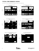
SIGNAL BALANCE RATIO
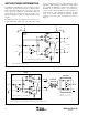
Signal balance ratio (SBR) measures the symmetry of the
output signals under loaded conditions.
To measure SBR an
input signal is applied and the outputs are summed as shown
in Figure 5. V
OUT
should be zero since each output ideally
is exactly equal and opposite. However, an error signal
results from any imbalance in the outputs. This error is
quantified by SBR. The impedances of the DRV134’s out
put stages are closely matched by laser trimming to mini-
mize SBR errors. In an application, SBR also depends on the
balance of the load network.
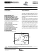
SINGLE-ENDED OPERATION
The DRV134 can be operated in single-ended mode without
degrading output drive capability. Single-ended operation
requires that the unused side of the output pair be grounded
(both the V
O
and Sense pins) to a low impedance return path.
Gain remains +6dB. Grounding the negative outputs as
shown in Figure 6 results in a noninverted output signal
(G = +2) while grounding the positive outputs gives an
inverted output signal (G = –2).
FIGURE 6. Typical Single-Ended Application.
FIGURE 5. Signal Balance Ratio Test Circuit.
600Ω
V
OUT
= 2V
IN
V
IN
V+
V–
DRV134
8
1
7
2
G = +6dB
4
5
6
3
For best rejection of line noise and hum differential mode
operation is recommended. However, single-ended perfor-
mance is adequate for many applications. In general single-
ended performance is comparable to differential mode (see
THD+N typical performance curves), but the common-
mode and noise rejection inherent in balanced-pair systems
is lost.
CABLE
The DRV134 is capable of driving large signals into 600Ω
loads over long cables. Low impedance shielded audio
cables such as the standard Belden 8451 or 9452 (or similar)
are recommended, especially in applications where long
cable lengths are required.
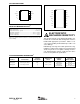
THERMAL PERFORMANCE
The DRV134 and DRV135 have robust output drive capa-
bility and excellent performance over temperature. In most
applications there is no significant difference between the
DIP, SOL-16, and SO-8 packages. However, for applica-
tions with extreme temperature and load conditions, the
SOL-16 (DRV134UA) or DIP (DRV134PA) packages are
recommended. Under these conditions, such as loads greater
than 600Ω or very long cables, performance may be de-
graded in the SO-8 (DRV135UA) package.
LAYOUT CONSIDERATIONS
A driver/receiver balanced-pair (such as the DRV134 and
INA137) rejects the voltage differences between the grounds
at each end of the cable, which can be caused by ground
currents, supply variations, etc. In addition to proper bypass-
ing, the suggestions below should be followed to achieve
optimal OCMR and noise rejection.
• The DRV134 input should be driven by a low impedance
source such as an op amp or buffer.
• As is the case for any single-ended system, the source’s
common should be connected as close as possible to the
DRV134’s ground. Any ground offset errors in the source
will degrade system performance.
• Symmetry on the outputs should be maintained.
• Shielded twisted-pair cable is recommended for all appli-
cations. Physical balance in signal wiring should be main-
tained. Capacitive differences due to varying wire lengths
may result in unequal noise pickup between the pair and
degrade OCMR. Follow industry practices for proper sys-
tem grounding of the cables.
V
OUT
V
IN
( )
600Ω
300Ω
(1)
300Ω
(1)
V
OUT
SBR = –20 Log at f = 1kHz
V
IN
= 10Vp-p
+V
O
–V
O
DRV134
1µF
+18V
6
8
1
7
2
1µF
–18V
Gnd
5
4
3
NOTE: (1) Matched to 0.1%.