
Datasheet
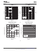

ActualSize
9mmSquare
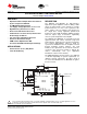
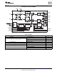
1 µF
AVDD
AGND (Connect to PowerPAD)
ROSC
COSC
AREF
IN+
IN−IN−
FAULT1
FAULT0
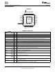
PVDD
PVDD
PVDD
H/C
H/C
H/C
H/C
PGND
PGND
PGND
PGND
PGND
PGND
PWM
PWM
PWM
PWM
PVDD
PVDD
PVDD
FREQ
120 kΩ
220 pF
1 µF
Shutdown Control
1 kΩ
1 kΩ
DC Control
Voltage
10 µF
V
DD
10 µH
1 µF
FAULT1
FAULT0
To TEC or Laser
Diode Anode
To TEC or Laser
Diode Cathode
1 µF
SHUTDOWN
INT/EXT
DRV593
DRV594
10 µF
DRV593
DRV594
www.ti.com
SLOS401C –OCTOBER 2002–REVISED JULY 2010
±3-A HIGH-EFFICIENCY PWM POWER DRIVER
Check for Samples: DRV593, DRV594
1
FEATURES
DESCRIPTION
2
• Operation Reduces Output Filter Size and Cost
by 50% Compared to DRV591
The DRV593 and DRV594 are high-efficiency,
high-current power amplifiers ideal for driving a wide
• ±3-A Maximum Output Current
variety of thermoelectric cooler elements in systems
• Low Supply Voltage Operation: 2.8 V to 5.5 V
powered from 2.8 V to 5.5 V. The operation of the
• High Efficiency Generates Less Heat
device requires only one inductor and capacitor for
• Overcurrent and Thermal Protection the output filter, saving significant printed-circuit
board area. Pulse-width modulation (PWM) operation
• Fault Indicators for Overcurrent, Thermal and
and low output stage on-resistance significantly
Undervoltage Conditions
decrease power dissipation in the amplifier.
• Two Selectable Switching Frequencies
The DRV593 and DRV594 are internally protected
• Internal or External Clock Sync
against thermal and current overloads. Logic-level
• PWM Scheme Optimized for EMI
fault indicators signal when the junction temperature
has reached approximately 128°C to allow for
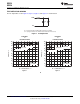
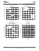
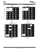
• 9×9 mm PowerPAD™ Quad Flatpack Package
system-level shutdown before the amplifier's internal
thermal shutdown circuitry activates. The fault
APPLICATIONS
indicators also signal when an overcurrent event has
• Thermoelectric Cooler (TEC) Driver
occurred. If the overcurrent circuitry is tripped, the
• Laser Diode Biasing
devices automatically reset (see application
information section for more details).
The PWM switching frequency may be set to 500 kHz
or 100 kHz depending on system requirements. To
eliminate external components, the gain is fixed at
2.3 V/V for the DRV593. For the DRV594, the gain is
fixed at 14.5 V/V.
1
Please be aware that an important notice concerning availability, standard warranty, and use in critical applications of Texas
Instruments semiconductor products and disclaimers thereto appears at the end of this data sheet.
2PowerPAD is a trademark of Texas Instruments.
PRODUCTION DATA information is current as of publication date.
Copyright © 2002–2010, Texas Instruments Incorporated
Products conform to specifications per the terms of the Texas
Instruments standard warranty. Production processing does not
necessarily include testing of all parameters.