
Datasheet

User's Guide
SLOU215 – January 2008
DRV601EVM
This user’s guide describes the operation of the DRV601EVM stereo line driver evaluation module and
provides measurement data and design information such as the schematic, bill of materials, and
printed-circuit board layout.
Contents
1 Overview ...................................................................................................................... 2
2 Quick Setup Guide........................................................................................................... 3
3 Shutdown ..................................................................................................................... 5
4 Component Selection ....................................................................................................... 5
5 Layout Recommendations .................................................................................................. 7
6 DRV601EVM Performance ................................................................................................. 8
7 Related Documentation from Texas Instruments ...................................................................... 19
8 Design Documentation .................................................................................................... 19
List of Figures
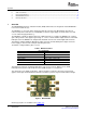
1 DRV601EVM ................................................................................................................. 2
2 DRV601 Functional Block Diagram ....................................................................................... 3
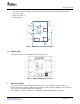
3 DRV601EVM Physical Structure ........................................................................................... 3
4 Power-Up/Down Sequence ................................................................................................. 5
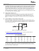
5 Second-Order, Active Low-Pass Filter .................................................................................... 6
6 THD+N vs Voltage (600 Ω ) ................................................................................................. 9
7 THD+N vs Voltage (600 Ω ) ................................................................................................. 9
8 THD+N vs Voltage (100-k Ω load) ........................................................................................ 10
9 THD+N vs Voltage (100- Ω load) Linear Scale ......................................................................... 10
10 THD+N vs Voltage (600- Ω Load) ........................................................................................ 11
11 THD+N vs Voltage (100-k Ω Load) ....................................................................................... 11
12 THD+N vs Frequency (600- Ω Load) ..................................................................................... 12
13 THD+N vs Frequency (600- Ω Load) Using X7R Input Capacitors .................................................. 12
14 FFT Spectrum With –60-dBFS Tone .................................................................................... 13
15 Idle Noise FFT Spectrum (BTL) .......................................................................................... 13
16 Channel Separation ........................................................................................................ 14
17 Channel Separation, 10x Lower Feedback Impedance ............................................................... 15
18 Frequency Response ...................................................................................................... 15
19 Phase Response ........................................................................................................... 16
20 Pop/Click (Enable) ......................................................................................................... 17
21 Pop/Click (Disable) ......................................................................................................... 18
22 DRV601EVM PCB Component Placement Top ........................................................................ 21
23 PCB Top Layer ............................................................................................................. 21
24 PCB Bottom Layer ......................................................................................................... 22
List of Tables
1 DRV601 Features ............................................................................................................ 2
2 Recommended Supply Voltage ............................................................................................ 5
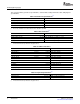
3 DRV601EVM Specification ................................................................................................. 6
4 General Test Specifications ................................................................................................ 8
PurePath Digital, DirectPath, FilterPro are trademarks of Texas Instruments.
SLOU215 – January 2008 DRV601EVM 1
Submit Documentation Feedback