
Datasheet

Design Documentation
www.ti.com
7.3 PCB Layers
Gerber files are available for download at the DRV632EVM product folder page on the TI Web site.
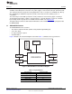
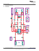
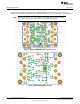
Component placement and board layout are illustrated in Figure 8, Figure 9, and Figure 10, respectively.
NOTE: Board layouts are not to scale. These figures are intended to show how the board is laid
out; they are not intended to be used for manufacturing DRV632EVM PCBs.
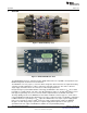
Figure 8. DRV632EVM PCB Component Placement
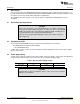
Figure 9. DRV632EVM PCB Top Layer
10
DRV632EVM Evaluation Module SLOU301–January 2010
Submit Documentation Feedback
© 2010, Texas Instruments Incorporated