
Datasheet

Quick Setup
www.ti.com
2 Quick Setup
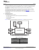
This section describes the DRV632EVM board with regard to the power supply and system interfaces. It
provides information about handling and unpacking the DRV632EVM, absolute operating conditions, and a
description of the factory default switch and jumper configurations.
The following subsections provide a step-by-step guide to configuring the DRV632EVM for device
evaluation.
2.1 Electrostatic Discharge Notice
CAUTION
Many of the components on the DRV632EVM are susceptible to damage by
electrostatic discharge (ESD). Customers are advised to observe proper ESD
handling precautions when unpacking and handling the EVM, including the use
of a grounded wrist strap at an approved ESD workstation.
Failure to observe proper ESD handling procedures may result in damage to
EVM components.
2.2 Unpacking the EVM
On opening the DRV632EVM package, ensure that the following items are included:
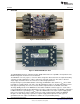
• One DRV632EVM evaluation board, including:
– One DRV632PW device
If either item is missing, contact the Texas Instruments Product Information Center nearest you to inquire
about a replacement.
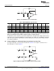
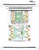
2.3 Power-Supply Setup
A single power supply is required to power up the EVM. The power supply is connected to the EVM board
using a two-pin, 2,54-mm header (J1). Table 2 lists the recommended supply voltage.
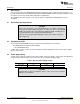
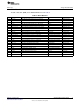
Table 2. Recommended Supply Voltage
Description Voltage Limitations Current Requirement Cable
Power supply 3.3 V 0.10 A —
CAUTION
Applying voltages above the limitations given in Table 2 may cause permanent
damage to your hardware.
4
DRV632EVM Evaluation Module SLOU301–January 2010
Submit Documentation Feedback
© 2010, Texas Instruments Incorporated