
Datasheet

R
2
R
1
R
3
C
2
C
X
C
1
C
3
DRV632
R
2
R
2
R
1
R
3
C
1
C
1
C
3
R
1
R
3
C
3
-In
+In
C
2
DRV632
Component Selection
www.ti.com
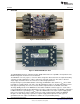
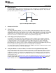
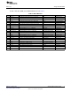
Figure 5. Second-Order, Active Low-Pass Filter
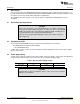
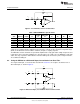
Table 3. DRV632EVM Filter Specifications
Single
Ended Differential
Gain High Pass Low Pass C1 C2 C2 C3 R1 R2 R3
–1 V/V 16 Hz 40 kHz 100 pF 680 pF 270 pF 1 mF 10 kΩ 10 kΩ 24 kΩ
–1.5 V/V 19 Hz 40 kHz 68 pF 680 pF 270 pF 1 mF 8.2 kΩ 12 kΩ 30 kΩ
–2 V/V 11 Hz 30 kHz 47 pF 470 pF 180 pF 1 mF 15 kΩ 30 kΩ 43 kΩ
–3.33 V/V 12 Hz 30 kHz 33 pF 470 pF 180 pF 1 mF 13 kΩ 43 kΩ 43 kΩ
–10 V/V 15 Hz 30 kHz 22 pF 1 nF 330 pF 2.2 mF 4.7 kΩ 47kΩ 27 kΩ
The resistor values must be low value to achieve low noise, but must be of high enough value to obtain a
small size ac-coupling capacitor. With the proposed values of 15 kΩ, 30 kΩ, and 43 kΩ, a dynamic range
(DYR) of 102 dB can be achieved with a small 2.2-mF input ac-coupling capacitor.
The MFB filter structure demands an operational amplifier that is unity-gain stable at high frequencies; this
requirement can be relaxed by adding the C
X
capacitor value to be equal to C1. The DRV632 is unity-gain
stable, but stray capacitance and inductance from the PCB layout can affect the phase margin. Therefore,
TI recommends adding C
X
.
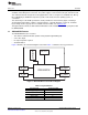
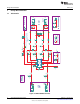
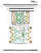
4.4 Using the DRV632 as a Differential Input, Second-Order Low-Pass Filter
The single-ended input, second-order filter described in Section 4.3 can easily be extended to have a
differential input, as shown in Figure 6.
Figure 6. Differential Input, Second-Order Active Low-Pass Filter
6
DRV632EVM Evaluation Module SLOU301–January 2010
Submit Documentation Feedback
© 2010, Texas Instruments Incorporated