
Datasheet

www.ti.com
Layout Recommendations
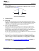
C
2
can be split into separate capacitors to ground with the double value; this technique increases the
common-mode filtering. Another capacitor, C
X
, set equal to C
1
can continue to be used from the negative
input to ground to limit the high-frequency gain to 2.
As with the single-ended input, the differential input filter component values can be calculated with the
help of the TI FilterPro active filter design program available on the TI Web site.
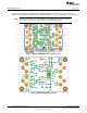
5 Layout Recommendations
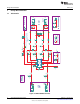
5.1 GND Connections
The GND pins of the DRV632 must be routed separately back to the decoupling capacitor in order to
facilitate proper device operation. If the GND pins are connected directly to each other, the device
functions without risk of failure, but noise and THD performance can be reduced.
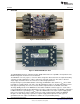
On the DRV632EVM, a star ground routing pattern is used; the star point is located directly below the
DRV632 device itself.
6 Related Documentation from Texas Instruments
The following related documents are available through the Texas Instruments Web site at
http://www.ti.com.These documents have detailed descriptions of the integrated circuits used in the design
of the DRV632EVM.
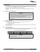
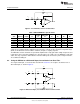
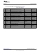
Table 4. Related Documentation
Part Number Literature Number
DRV632 SLOS681 data sheet
7
SLOU301–January 2010 DRV632EVM Evaluation Module
Submit Documentation Feedback
© 2010, Texas Instruments Incorporated