MSP430 Hardware Tools User's Guide Literature Number: SLAU278I May 2009 – Revised May 2012
Contents ....................................................................................................................................... 7 Get Started Now! ............................................................................................................... 11 1.1 Flash Emulation Tool (FET) Overview .................................................................................. 12 1.2 Kit Contents, MSP-FET430PIF ...........................................................................
www.ti.com B.16 B.17 B.18 B.19 B.20 B.21 B.22 B.23 B.24 B.25 B.26 B.27 B.28 B.29 B.30 B.31 B.32 B.33 MSP-TS430PM64A ....................................................................................................... 78 MSP-TS430RGC64B ..................................................................................................... 81 MSP-TS430RGC64C ..................................................................................................... 84 MSP-TS430RGC64USB ...........................
www.ti.com List of Figures 2-1. Signal Connections for 4-Wire JTAG Communication ................................................................ 23 2-2. Signal Connections for 2-Wire JTAG Communication (Spy-Bi-Wire) Used by MSP430F2xx and MSP430F4xx Devices .................................................................................................... 24 2-3. Signal Connections for 2-Wire JTAG Communication (Spy-Bi-Wire) Used by MSP430F5xx and MSP430F6xx Devices .................................
www.ti.com B-44. MSP-TS430PN80USB Target Socket Module, PCB.................................................................. 98 ............................................................. .................................................................... MSP-TS430PZ100A Target Socket Module, Schematic............................................................ MSP-TS430PZ100A Target Socket Module, PCB ...................................................................
www.ti.com List of Tables Flash Emulation Tool (FET) Features 1-2. Individual Kit Contents, MSP-TS430xx ................................................................................. 17 B-1. MSP-TS430D8 Bill of Materials .......................................................................................... 35 B-2. MSP-TS430PW14 Bill of Materials ...................................................................................... 38 B-3. MSP-TS430L092 Bill of Materials .....................
Preface SLAU278I – May 2009 – Revised May 2012 Read This First About This Manual This manual describes the hardware of the Texas Instruments MSP-FET430 Flash Emulation Tool (FET). The FET is the program development tool for the MSP430 ultra-low-power microcontroller. Both available interface types, the parallel port interface and the USB interface, are described. How to Use This Manual Read and follow the instructions in Chapter 1.
How to Use This Manual • • • • • • • • • • • • • • • • www.ti.
Information About Cautions and Warnings www.ti.
If You Need Assistance www.ti.
Chapter 1 SLAU278I – May 2009 – Revised May 2012 Get Started Now! This chapter lists the contents of the FET and provides instruction on installing the hardware. Topic 1.1 1.2 1.3 1.4 1.5 1.6 1.7 1.8 1.9 1.10 1.11 1.12 1.13 1.14 1.15 1.16 1.17 1.18 1.19 ........................................................................................................................... Flash Emulation Tool (FET) Overview ..................................................................
Flash Emulation Tool (FET) Overview 1.1 www.ti.com Flash Emulation Tool (FET) Overview TI offers several flash emulation tools according to different requirements.
Kit Contents, MSP-FET430PIF www.ti.com 1.2 Kit Contents, MSP-FET430PIF • • • • One One One One READ ME FIRST document MSP-FET430PIF interface module 25-conductor cable 14-conductor cable NOTE: This part is obsolete and is not recommended to use in new design. 1.3 Kit Contents, eZ430-F2013 • • 1.4 Kit Contents, eZ430-T2012 • 1.
Kit Contents, eZ430-Chronos-xxx 1.8 www.ti.
Kit Contents, MSP-FET430xx www.ti.com 1.10 Kit Contents, MSP-FET430xx 'U8, 'U14, 'U092, 'U24, 'U28, 'U28A, 'U38, 'U23x0, 'U40, 'U40A, 'U48, 'U48B, 'U64, 'U64A, 'U64B, 'U64C, 'U64USB, 'U80, 'U80USB, 'U100, 'U100A, 'U100B, 'U100C, 'U5x100, 'U100USB • One READ ME FIRST document • One MSP-FET430UIF USB interface module. This is the unit that has a USB B-connector on one end of the case, and a 2×7-pin male connector on the other end of the case. • One USB cable • One 32.
Kit Contents, FET430F6137RF900 www.ti.com 1.11 Kit Contents, FET430F6137RF900 • • • • • • • • • • • 16 One READ ME FIRST document One legal notice One MSP-FET430UIF interface module Two EM430F6137RF900 target socket modules. This is the PCB on which is soldered a CC430F6137 device in a 64-pin RGC package. A 2×7-pin male connector is also present on the PCB Two CC430EM battery packs Four AAA batteries Two 868- or 915-MHz antennas Two 32.
Kit Contents, Sub-1 GHz RF Spectrum Analyzer Tool (MSP-SA430-SUB1GHZ) www.ti.com 1.12 Kit Contents, Sub-1 GHz RF Spectrum Analyzer Tool (MSP-SA430-SUB1GHZ) • • • • • MSP-SA430-SUB1GHZ Spectrum Analyzer Antenna USB Cable CD with a Microsoft Windows Graphical User Interface (GUI) and Documentation Quick start guide 1.
Kit Contents, MSP-TS430xx www.ti.com Table 1-2.
Kit Contents, EM430Fx1x7RF900 www.ti.com 1.14 Kit Contents, EM430Fx1x7RF900 • • • • • • • • One READ ME FIRST document One legal notice Two target socket module MSP-EM430F5137RF900: Two EM430F5137RF900 target socket modules. This is the PCB on which is soldered a CC430F5137 device in a 48-pin RGZ package. A 2×7-pin male connector is also present on the PCB MSP-EM430F6137RF900: Two EM430F6137RF900 target socket modules. This is the PCB on which is soldered a CC430F6137 device in a 64-pin RGC package.
Hardware Installation, eZ430-XXXX, MSP-EXP430G2, MSP-EXP430FR5739, MSP-EXP430F5529 www.ti.com 1.17 Hardware Installation, eZ430-XXXX, MSP-EXP430G2, MSP-EXP430FR5739, MSPEXP430F5529 To install eZ430-XXXX, MSP-EXP430G2, MSP-EXP430FR5739, MSP-EXP430F5529 tools follow instructions 1 and 2 of Section 1.16 1.18 Hardware Installation, MSP-FET430Uxx, MSP-TS430xxx, FET430F6137RF900, EM430Fx137RF900 Follow these steps to install the hardware for the MSP-FET430Uxx and MSP-TS430xxx tools: 1.
Chapter 2 SLAU278I – May 2009 – Revised May 2012 Design Considerations for In-Circuit Programming This chapter presents signal requirements for in-circuit programming of the MSP430. Topic 2.1 2.2 2.3 ........................................................................................................................... Page Signal Connections for In-System Programming and Debugging ............................ 22 External Power .......................................................................
Signal Connections for In-System Programming and Debugging 2.1 www.ti.com Signal Connections for In-System Programming and Debugging MSP-FET430PIF, MSP-FET430UIF, MSP-GANG, MSP-GANG430, MSP-PRGS430 With the proper connections, the debugger and an FET hardware JTAG interface (such as the MSPFET430PIF and MSP-FET430UIF) can be used to program and debug code on the target board.
Signal Connections for In-System Programming and Debugging www.ti.com VCC J1 (see Note A) VCC/AVCC/DVCC J2 (see Note A) R1 47 kW (see Note B) C2 10 µF C3 0.1 µF MSP430Fxxx JTAG VCC TOOL VCC TARGET TEST/VPP RST/NMI 2 1 4 3 6 5 8 7 10 9 12 11 14 13 TDO/TDI TDO/TDI TDI/VPP TDI/VPP TMS TMS TCK TCK GND RST (see Note D) TEST/VPP (see Note C) C1 10 nF/2.
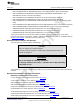
Signal Connections for In-System Programming and Debugging www.ti.com VCC J1 (see Note A) VCC / AV CC / DVCC J2 (see Note A) R1 47kΩ See Note B C2 10μF C3 0.1μF MSP430Fxxx JTAG VCC TOOL VCC TARGET TEST/VPP 2 1 4 3 6 5 8 7 10 9 12 11 14 13 TDO/TDI RST/NMI/SBWTDIO TCK GND R2 330Ω TEST/SBWTCK C1 2.2 nF See Note B VSS / AV SS / DVSS A Make connection J1 if a local target power supply is used, or make connection J2 if the target is powered from the debug or programming adapter.
Signal Connections for In-System Programming and Debugging www.ti.com VCC J1 (see Note A) VCC / AV CC / DVCC J2 (see Note A) R1 47kΩ See Note B C2 10µF C3 0.1μF MSP430Fxxx JTAG VCC TOOL VCC TARGET 2 1 4 3 6 5 8 7 10 9 12 11 14 13 TDO/TDI RST/NMI/SBWTDIO TCK GND TEST/SBWTCK C1 2.2 nF See Note B VSS / AV SS / DVSS A Make connection J1 if a local target power supply is used, or make connection J2 if the target is powered from the debug or programming adapter.
External Power 2.2 www.ti.com External Power The MSP-FET430UIF can supply targets with up to 60 mA through pin 2 of the 14-pin connector. VCC for the target can be selected between 1.8 V and 5 V in steps of 0.1 V. Alternatively, the target can be supplied externally. In this case, the external voltage should be connected to pin 4 of the 14-pin connector. The MSP-FET430UIF then adjusts the level of the JTAG signals to external VCC automatically.
Appendix A SLAU278I – May 2009 – Revised May 2012 Frequently Asked Questions and Known Issues This appendix presents solutions to frequently asked questions regarding the MSP-FET430 hardware. Topic A.1 A.2 ........................................................................................................................... Page Hardware FAQs ................................................................................................. 28 Known Issues ...........................................
Hardware FAQs A.1 www.ti.com Hardware FAQs 1. MSP430F22xx Target Socket Module (MSP-TS430DA38) – Important Information Due to the large capacitive coupling introduced by the device socket between the adjacent signals XIN/P2.6 (socket pin 6) and RST/SBWTDIO (socket pin 7), in-system debugging can disturb the LFXT1 low-frequency crystal oscillator operation (ACLK). This behavior applies only to the Spy-Bi-Wire (2-wire) JTAG configuration and only to the period while a debug session is active.
Hardware FAQs www.ti.com 11. Information memory may not be blank (erased to 0xFF) when the device is delivered from TI. Customers should erase the information memory before its first use. Main memory of packaged devices is blank when the device is delivered from TI. 12. The device current is bigger then expected. The device current measurement may not be accurate with connected debugger to the device. For accurate measurement disconnect the debugger. 13.
Known Issues A.2 www.ti.com Known Issues MSP-FET430UIF Current detection algorithm of the UIF firmware Problem Description If high current is detected, the ICC monitor algorithm stays in a loop of frequently switching on and off the target power supply. This power switching puts some MSP430 devices such as the MSP430F5438 in a state that requires a power cycle to return the device to JTAG control.
Appendix B SLAU278I – May 2009 – Revised May 2012 Hardware This appendix contains information relating to the FET hardware, including schematics, PCB pictorials, and bills of materials. All other tools, such as the eZ430 series, are described in separate product-specific user's guides.
Appendix B Topic www.ti.com ........................................................................................................................... B.1 B.2 B.3 B.4 B.5 B.6 B.7 B.8 B.9 B.10 B.11 B.12 B.13 B.14 B.15 B.16 B.17 B.18 B.19 B.20 B.21 B.22 B.23 B.24 B.25 B.26 B.27 B.28 B.29 B.30 B.31 B.32 B.33 32 Page MSP-TS430D8 ................................................................................................... 33 MSP-TS430PW14 .............................................................
MSP-TS430D8 B.1 MSP-TS430D8 www.ti.com Vcc J5 3 2 1 14 12 10 8 6 4 2 SBW 13 11 9 7 5 3 1 GND SBWTCK RST/SBWTDIO TST/SBWTCK to measure supply current J6 J4 R2 330R 1 2 3 4 TST/SBWTCK FE4L J1 VCC430 P1.2 P1.5 P1.6 U1 RST/SBWTDIO R5 47K MSP-TS430D8 DVCC P1.2/TA1/A2 P1.5/TA0/A5/SCLK P1.6/TA1/A6/SDO/SCL DNP GND C8 2.2nF 1 2 3 4 Socket: YA MAICHI Type: IC369-0082 DVSS TST/SBWTCK RST/SBWTDIO P1.7/A7/SDI/SDA 8 7 6 5 GND GND TST/SBWTCK RST/SBWTDIO P1.
MSP-TS430D8 www.ti.com 14 pin connector for debugging only in Spy-Bi-Wire mode (4 Wire JTAG not available) D1 LED connected to P1.2 Connector J5 External power connector Jumper JP3 to "ext" Jumper JP2 Open to disconnect LED Orient Pin 1 of MSP430 device Figure B-2.
MSP-TS430D8 www.ti.com Table B-1. MSP-TS430D8 Bill of Materials Position No. per Board Ref Des Description DigiKey Part No. Comment 1 J4, J6 2 2-pin header, male, TH SAM1035-02-ND place jumper on header 2 J5 1 3-pin header, male, TH SAM1035-03-ND place jumper on pins 1-2 3 SBW 1 10-pin connector, male, TH HRP10H-ND 4 J3 1 3-pin header, male, TH SAM1035-03-ND 5 C8 1 2.
MSP-TS430PW14 B.2 www.ti.com MSP-TS430PW14 Figure B-3.
MSP-TS430PW14 www.ti.com Connector J3 External power connector Jumper J5 to 'ext' LED connected to P1.0 Jumpers J7 to J12 Close 1-2 to debug in Spy-Bi-Wire Mode. Close 2-3 to debug in 4-wire JTAG mode. Jumper J4 Open to disconnect LED Orient Pin 1 of MSP430 device Jumper J6 Open to measure current Figure B-4.
MSP-TS430PW14 www.ti.com Table B-2. MSP-TS430PW14 Bill of Materials Position Ref Des No. per Board 1 C1, C2 0 12pF, SMD0805 2 C7 1 10uF/10V, Tantal Size B 511-1463-2-ND 3 C3, C5 1 100nF, SMD0805 4 C8 0 2.2nF, SMD0805 5 D1 1 green LED, SMD0603 475-1056-2-ND 6 J1, J2 0 7-pin header, TH SAM1029-07NDSAM1213-07-ND DNP: Headers and receptacles enclosed with kit.
MSP-TS430L092 www.ti.com B.3 MSP-TS430L092 Figure B-5.
MSP-TS430L092 www.ti.com Settings of the MSP-TS430L092 Target Socket Figure B-6 shows the PCB layout of the MSP-TS430L092 target socket. The following pinning is recommended: • JP1 is write enable for the EPROM. If this is not set, the EPROM can only be read. • JP2 and JP3 connect device supply with boost converter. They can be opened to measure device current consumption. For default operation, they should be closed. Figure B-6.
MSP-TS430L092 www.ti.com Table B-3. MSP-TS430L092 Bill of Materials Pos. Ref Des No. No. Per Board 1 C1, C2 2 330nF, SMD0603 2 C5 1 100n, SMD0603 3 C6 1 10u, SMD0805 4 C10 1 100n, SMD0603 5 EEPROM1 1 M95512 SO08 (SO8) 7 J1, J2 2 Description DigiKey Part No. ST Micro M95160R Comment Digikey: 497-8688-1-ND DNP: headers and receptacles enclosed with kit. Keep vias free of solder.
MSP-TS430L092 Active Cable B.4 www.ti.com MSP-TS430L092 Active Cable Figure B-7.
MSP-TS430L092 Active Cable www.ti.com Figure B-8 shows the PCB layout for the Active Cable. The following pinning is possible: • JP1 has two jumpers (Jumper 1 and Jumper 2) that can be set as shown in Table B-4. Table B-4. MSP-TS430L092 JP1 Settings • Jumper 1 Jumper 2 Description Off Off The active cable has no power and does not function. Off On The active cable receives power from target socket. For this option, the target socket must have its own power supply.
MSP-TS430L092 Active Cable www.ti.com Table B-5. MSP-TS430L092 Active Cable Bill of Materials 44 Pos. Ref Des No. Per Board 1 C1, C3, C5, C6 4 100nF, SMD0603 2 C2, C4 2 1uF, SMD0805 3 R1, R10 2 10K, SMD0603 4 R2 1 4K7, SMD0603 5 R5, R6, R7, R9 4 100, SMD0603 6 R8 1 680k, SMD0603 7 R11, R15 2 1K, SMD0603 8 R12 0 SMD0603 DNP 9 R13 0 SMD0603 DNP 10 R14 1 0, SMD0603 11 IC1 1 SN74AUC1G04DBVR 12 IC2, IC3, IC4 3 SN74AUC2G125DCTR Description DigiKey Part No.
MSP-TS430PW24 www.ti.com B.5 MSP-TS430PW24 Figure B-9.
MSP-TS430PW24 www.ti.com Connector J5 External power connector Jumper JP1 to "ext" Jumper JP2 Open to measure current Jumpers JP4 to JP9 Close 1-2 to debug in Spy-Bi-Wire mode Close 2-3 to debug in 4-wire JTAG mode Orient Pin 1 of MSP430 device D1 LED connected to P1.0 Jumper JP3 Open to disconnect LED Figure B-10.
MSP-TS430PW24 www.ti.com Table B-6. MSP-TS430PW24 Bill of Materials Position Ref Des No. per Board 1 C1, C2 0 12pF, SMD0805 2 C5 1 2.2nF, SMD0805 3 C3, C7 2 10uF/10V, SMD0805 4 C4, C6, C8 3 100nF, SMD0805 478-3351-2-ND 5 D1 1 green LED, SMD0805 P516TR-ND 6 J1, J2 0 12-pin header, TH "SAM1029-07NDSAM1213-07-ND" DNP: Headers and receptacles enclosed with kit. Keep vias free of solder.
MSP-TS430DW28 B.6 www.ti.com MSP-TS430DW28 Figure B-11.
MSP-TS430DW28 www.ti.com LED connected to P1.0 Jumper J4 Open to disconnect LED Jumper J5 Open to measure current Connector J3 External power connector Remove R8 and jumper R9 Orient Pin 1 of MSP430 device Figure B-12.
MSP-TS430DW28 www.ti.com Table B-7. MSP-TS430DW28 Bill of Materials Position Ref Des No. per Board 1 C1, C2 0 12pF, SMD0805 2 C5 1 100nF, SMD0805 3 C7 1 10uF/10V Tantal Elko B 4 C8 1 10nF SMD0805 5 D1 1 LED3 T1 3mm yellow RS: 228-4991 6 Q1 0 QUARZ, Crystal Micro Crystal MS1V-T1K 32.768kHz, C(Load) = DNP: Cover holes while soldering 12.5pF 7 J1, J2 2 14-pin header, TH male DNP: Headers and receptacles enclosed with kit. Keep vias free of solder.
MSP-TS430PW28 www.ti.com B.7 MSP-TS430PW28 Figure B-13.
MSP-TS430PW28 www.ti.com Jumper JP4 to JP9: Close 1-2 to debug in Spy-Bi-Wire mode Close 2-3 to debug in 4-wire JTAG mode Jumper JP1 1-2 (int): Power supply via JTAG interface 2-3 (ext): External Power Supply Jumper JP2 Open to measure current Orient Pin 1 of Device Jumper JP3 Open to disconnect LED LED D1 connected to P5.1 Figure B-14.
MSP-TS430PW28 www.ti.com Table B-8. MSP-TS430PW28 Bill of Materials Pos. Ref Des No. per Board 1 C1, C2 0 12pF, SMD0805 2 C3 1 10uF/10V Tantal Elko B 3 C4 1 100nF, SMD0805 4 C5 0 2.2nF, SMD0805 5 D1 1 LED green SMD0603 6 Q1 0 QUARZ, Crystal 7 J1, J2 7.1 (1) Description (1) DigiKey Part No. Comment DNP: C1, C2 , Cover holes while soldering DNP Micro Crystal MS1V-T1K 32.768kHz, C(Load) = 12.
MSP-TS430PW28A B.8 www.ti.com MSP-TS430PW28A Figure B-15.
MSP-TS430PW28A www.ti.com Jumper JP2 Open to measure current Orient Pin 1 of MSP430 device Connector J5 External power connector Jumper JP1 to "ext" Jumpers JP4 to JP9 Close 1-2 to debug in Spy-Bi-Wire mode Close 2-3 to debug in 4-wire JTAG mode Jumper JP3 Open to disconnect LED D1 LED connected to P1.0 Figure B-16.
MSP-TS430PW28A www.ti.com Table B-9. MSP-TS430PW28A Bill of Materials Position Ref Des No. per Board 1 C1, C2 0 12pF, SMD0805 2 C5 1 2.
MSP-TS430DA38 www.ti.com B.9 MSP-TS430DA38 Figure B-17.
MSP-TS430DA38 www.ti.com Jumpers JP4 to JP9 Close 1-2 to debug in Spy-Bi-Wire Mode, Close 2-3 to debug in 4-wire JTAG Mode LED connected to P1.0 Jumper JP3 Open to disconnect LED Orient pin 1 of MSP430 device Jumper JP2 Open to measure current Connector J3 External power connector Jumper JP1 to 'ext' Figure B-18.
MSP-TS430DA38 www.ti.com Table B-10. MSP-TS430DA38 Bill of Materials Pos. Ref Des No. per Board 1 C1, C2 0 12pF, SMD0805 2 C7 1 10uF/10V, Tantal Size B 511-1463-2-ND 3 C5 1 100nF, SMD0805 478-3351-2-ND 4 C8 0 2.2nF, SMD0805 5 D1 1 green LED, SMD0603 Description DigiKey Part No. Comment DNP DNP 475-1056-2-ND 6 J1, J2 0 19-pin header, TH "SAM1029-19NDSAM1213-19-ND" DNP: headers and receptacles enclosed with kit.Keep vias free of solder.
MSP-TS430QFN23x0 www.ti.com B.10 MSP-TS430QFN23x0 Figure B-19.
MSP-TS430QFN23x0 www.ti.com Connector J5 External power connector Jumper JP1 to 'ext' Jumper JP2 Open to measure current Jumper JP3 Open to disconnect LED LED connected to P1.0 Figure B-20.
MSP-TS430QFN23x0 www.ti.com Table B-11. MSP-TS430QFN23x0 Bill of Materials Pos. Ref Des No. per Board 1 C1, C2 0 12pF, SMD0805 2 C3 1 10uF/10V, Tantal Size B 511-1463-2-ND 3 C4 1 100nF, SMD0805 478-3351-2-ND 4 C5 1 10nF, SMD0805 478-1383-2-ND 5 D1 1 green LED, SMD0603 475-1056-2-ND DigiKey Part No. Comment DNP 6 J1, J2, J3, J4 0 10-pin header, TH DNP: headers and receptacles enclosed with SAM1034-10-NDSAM1212kit.Keep vias free of 10-ND solder.
MSP-TS430RSB40 www.ti.com B.11 MSP-TS430RSB40 Figure B-21.
MSP-TS430RSB40 www.ti.com Connector J5 External power connector Jumper JP1 to "ext" Jumper JP2 Open to measure current Jumpers JP4 to JP9 Close 1-2 to debug in Spy-Bi-Wire mode Close 2-3 to debug in 4-wire JTAG mode Orient Pin 1 of MSP430 device Jumper JP3 Open to disconnect LED D1 LED connected to P1.0 Figure B-22.
MSP-TS430RSB40 www.ti.com Table B-12. MSP-TS430RSB40 Bill of Materials Ref Des No. Per Board Description 1 C1, C2 0 12pF, SMD0805 2 C3, C7, C10, C12 3 10uF/10V, SMD 0805 445-1371-1-ND DNP C12 3 C4, C6, C8, C11 3 100nF, SMD0805 311-1245-2-ND DNP C11 4 C5 1 2.2nF, SMD0805 5 C9 1 470nF, SMD0805 6 D1 1 green LED, SMD0805 Pos. DigiKey Part No. Comment DNP: C1, C2 P516TR-ND 10-pin header, TH DNP: headers and receptacles enclosed with kit. Keep vias free of solder.
MSP-TS430RHA40A www.ti.com B.12 MSP-TS430RHA40A Figure B-23.
MSP-TS430RHA40A www.ti.com Connector J5 External power connector Jumper JP1 to "ext" Jumper JP2 Open to measure current Jumpers JP4 to JP9 Close 1-2 to debug in Spy-Bi-Wire mode Close 2-3 to debug in 4-wire JTAG mode D1 LED connected to P1.0 Jumper JP3 Open to disconnect LED Orient Pin 1 of MSP430 device Figure B-24.
MSP-TS430RHA40A www.ti.com Table B-13. MSP-TS430RHA40A Bill of Materials Position Ref Des No. per Board 1 C1, C2 0 12pF, SMD0805 DNP: C1, C2 2 C5 0 2.2nF, SMD0805 DNP C12 3 C3, C7 2 10uF/10V, SMD0805 5 4 C4, C6 2 100nF, SMD0805 5 C9 1 470nF, SMD0805 6 D1 1 green LED, SMD0805 7 J1, J2, J3, J4 4 10-pin header, TH DNP: headers and receptacles enclosed with kit. Keep vias free of solder.
MSP-TS430DL48 www.ti.com B.13 MSP-TS430DL48 Figure B-25.
MSP-TS430DL48 www.ti.com Jumper J5 Open to measure current LED connected to P1.0 Connector J3 External power connector Jumper JP1 to ‘ext’ Jumper J4 Open to disconnect LED Orient pin 1 of MSP430 device Figure B-26.
MSP-TS430DL48 www.ti.com Table B-14. MSP-TS430DL48 Bill of Materials Pos. Ref Des No. per Board 1 C1, C2 0 12pF, SMD0805 2 C4, C7 2 10uF/10V, Tantal Size B 511-1463-2-ND 3 C3, C5 2 100nF, SMD0805 478-3351-2-ND 4 C8 1 10nF, SMD0805 478-1383-2-ND 5 D1 1 yellow LED, TH, 3mm, T1 511-1251-ND Description DigiKey Part No. Comment DNP 6 J1, J2 0 24-pin header, TH DNP: Headers and receptacles enclosed with SAM1034-12-NDSAM1212kit.Keep vias free of 12-ND solder.
MSP-TS430RGZ48B www.ti.com B.14 MSP-TS430RGZ48B Figure B-27.
MSP-TS430RGZ48B www.ti.com Connector J5 External power connector Jumper JP1 to "ext" Jumpers JP5 to JP10 Close 1-2 to debug in Spy-Bi-Wire mode Close 2-3 to debug in 4-wire JTAG mode Jumper JP1 Open to measure current Orient Pin 1 of MSP430 device Jumper JP2 Open to disconnect LED D1 LED connected to P1.0 Figure B-28.
MSP-TS430RGZ48B www.ti.com Table B-15. MSP-TS430RGZ48B Bill of Materials Position Ref Des No. per Board 1 C1, C2 0 12pF, SMD0805 DNP 2 C3, C4 0 47pF, SMD0805 DNP 3 C6, C7, C12 3 10uF/6.3V, SMD0805 4 C5, C11, C13, C14 4 100nF, SMD0805 5 C8 1 2.2nF, SMD0805 6 C9 1 470nF, SMD0805 478-1403-2-ND 7 D1 1 green LED, SMD0805 P516TR-ND 8 J1, J2, J3, J4 0 12-pin header, TH SAM1029-12-ND (Header) SAM1213-12ND (Receptacle) DNP: Headers and receptacles enclosed with kit.
MSP-TS430PM64 www.ti.com B.15 MSP-TS430PM64 NOTE: Connections between the JTAG header and pins XOUT and XIN are no longer required and should not be made. Figure B-29.
MSP-TS430PM64 www.ti.com Connector J5 External power connection Remove R8 and jumper R9 LED connected to pin 12 Jumper J7 Open to measure current Jumper J6 Open to disconnect LED Orient Pin 1 of MSP430 device Figure B-30.
MSP-TS430PM64 www.ti.com Table B-16. MSP-TS430PM64 Bill of Materials Pos. Ref Des No. per Board 1 C1, C2 0 12pF, SMD0805 DNP 1.1 C3, C4 0 47pF, SMD0805 DNP: Only recommendation. Check your crystal spec. 2 C6, C7 1 10uF/10V, Tantal Size B 511-1463-2-ND 3 C5 1 100nF, SMD0805 478-3351-2-ND 4 C8 1 10nF, SMD0805 478-1383-2-ND 5 C9 1 470nF, SMD0805 478-1403-2-ND 6 D1 1 green LED, SMD0805 P516TR-ND Description DigiKey Part No.
MSP-TS430PM64A www.ti.com B.16 MSP-TS430PM64A Figure B-31.
MSP-TS430PM64A www.ti.com Jumper JP3 1-2 (int): Power supply via JTAG interface 2-3 (ext): External Power Supply Jumper JP4 to JP9: Close 1-2 to debug in Spy-Bi-Wire mode Close 2-3 to debug in 4-wire JTAG mode Jumper JP2 Open to measure current Orient Pin 1 of Device Jumper JP1 Open to disconnect LED LED D1 connected to P5.1 Figure B-32.
MSP-TS430PM64A www.ti.com Table B-17. MSP-TS430PM64A Bill of Materials Pos. Ref Des No. per Board 1 C1, C2, 0 12pF, SMD0805 DNP 2 C3 0 2.2nF, SMD0805 DNP 3 C6, 1 10uF/10V, Tantal Size B 511-1463-2-ND 4 C4, C5 2 100nF, SMD0805 478-3351-2-ND 5 D1 1 green LED, SMD0805 P516TR-ND DigiKey Part No. Comment DNP: Headers and receptacles enclosed with kit. Keep vias free of solder.