Maintenance Manual Extensa 57x Series Notebook Computers 9811323-0001 May 1996
Copyright (©) 1996 Texas Instruments Incorporated All Rights Reserved — Printed in U.S.A. Extensa 57x Series Notebook Computers Maintenance Manual TI Part No. 9811323-0001 Original Issue: May 1996 Changes may be made periodically to the information in this publication. Such changes will be incorporated in new editions of this manual.
Contents Preface 1 General Description 1.1 . . . . Introduction . . . . . . . . . . . . . . . . . . . . . . . . . . . . . . . 1-1 1.2 . . . . Product Models . . . . . . . . . . . . . . . . . . . . . . . . . . . . . 1-1 1.3 . . . . International Product Versions . . . . . . . . . . . . . . . . . 1-2 1.4 . . . . Product Overview . . . . . . . . . . . . . . . . . . . . . . . . . . . 1-3 1.4.1 . . . External Ports . . . . . . . . . . . . . . . . . . . . . . . . . . . 1-5 1.4.2 . . . Glidepad Pointing Device .
2.5.1 . . . Installing an External Keyboard/Mouse . . . . . . . 2-4 2.5.2 . . . Installing External Parallel Printer . . . . . . . . . . . . 2-6 2.5.3 . . . Installing External Serial Port Device . . . . . . . . . 2-7 2.5.4 . . . Installing External SVGA Monitor . . . . . . . . . . . . 2-8 2.5.5 . . . Installing SIR Devices. . . . . . . . . . . . . . . . . . . . . . 2-9 2.6 . . . . Installing the AC Power Adapter . . . . . . . . . . . . . . . 2-10 2.7 . . . . Initial System Checkout . . . . . . . . . . .
4.2.4 . . . Hard Disk Subsystem . . . . . . . . . . . . . . . . . . . . . 4-6 4.2.5 . . . Floppy Diskette Drive Subsystem . . . . . . . . . . . . . 4-7 4.2.6 . . . CD-ROM Subsystem . . . . . . . . . . . . . . . . . . . . . . 4-7 4.2.7 . . . PCMCIA Subsystem . . . . . . . . . . . . . . . . . . . . . . . 4-7 4.2.8 . . . Sound Subsystem (Model Dependent) . . . . . . . . . 4-8 4.2.9 . . . Power Subsystem . . . . . . . . . . . . . . . . . . . . . . . . . 4-8 5 Troubleshooting Procedures 5.1 . . . . General . .
.5.7 . . . Removing and Replacing the LCD Status . . . . . . . Assembly . . . . . . . . . . . . . . . . . . . . . . . . . . . . . . . 6-11 6.5.8 . . . Removing/Replacing the Top Case Assembly . . . . 6-12 6.5.9 . . . Removing/Replacing the Glidepad Assembly . . . . 6-12 6.5.10 . . Removing/Replacing the IR/Sound Assembly . . . 6-12 6.5.11 . . Removing/Replacing the Power Supply Board . . . 6-13 6.5.12 . . Removing/Replacing the CMOS Battery . . . . . . . 6-13 6.5.13 . . Removing/Replacing the Main Board .
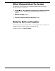
Preface Introduction This manual provides installation, operation and servicing data for the Extensa 57x Series Notebook Computers. Intended Audience This manual is primarily intended for use by qualified service technicians but contains information useful to non-technical users.
Other Manuals About the System The following documents provide additional information related to the Extensa 57x Series Notebooks: • Extensa 57x Series Notebook Computer User’s Reference Manual, contains reference information regarding the Extensa 57x series software.
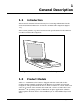
1 General Description 1.1 Introduction This manual contains field and factory level servicing information for the Texas Instruments Extensa 57x Series of Notebook Computers (Figure 1-1). This section provides a general overview and specifications for the Extensa 57x Series Notebook Computers. Figure 1-1 Extensa 57xSeries Notebook Computer 1.
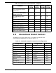
Table 1-1 Extensa 57x Series Notebook Computers Features Model 570CD 11.3" Dual Scan, SVGA Color LCD X Model 575CD Model Model 570CDT 575CDT X 10.4" Active Matrix (TFT), SVGA Color LCD X X 1.44 MB Floppy Drive Module X X X X CD-ROM Drive Module X X X X Windows 95 X X X X Application Software X 16-Bit Stereo Sound X X HDD 810 Million Bytes X X HDD 1200 Million Bytes 1.
1.4 Product Overview All members of the Extensa 57x Series are high performance notebooks powered by the Pentium Processor and Windows 95 Operating System software. As a standard feature, all members of the Extensa 57x family also contain the following features: • • 100 MHz Pentium Processor with 16K Internal Cache Memory. 8 MB of RAM memory standard, user-expandable to 40 MB (easy access via door at bottom of notebook). • 256 KB L2 Cache. • 128 bytes of battery-backed up CMOS RAM.
• • • • • AC Adapter with autosensing (100 VAC to 240 VAC, 50 to 60 Hz); 36 Watts of DC output power. 8.4 Volt, 4200 mAH capacity, Nickel-Metal Hydride (NiMH) primary battery pack. Provisions for secondary 10.8 Volt Lithium-Ion Battery Pack in Floppy Drive cavity (if Floppy Drive or CD ROM Player not installed). Power management features for longer portable operation away from AC power.
1.4.
1.4.2 Glidepad Pointing Device All members of the Extensa 57x family feature a built-in glidepad pointing device located near the center of the keyboard’s palmrest. With light finger pressure, the cursor can quickly be positioned to the desired point; a quick double tap on the glidepad and you have selected an object. Two select buttons (switches) are located along the front edge of the notebook for use in the traditional select/drag features of a mouse device. .
n Note: The Extensa Series Notebook Computer User’s Reference Manual contains descriptions of keyboard special function keys. Esc F2 F1 F3 @ 2 1 F4 F6 F5 % F8 & 7 ^6 5 4 3 F7 F9 8 7 9 Caps Lock Q W A F D S T R E Y U H G C X Z V B 4 J N * I 1 O 5 Ctrl Alt Pause Break Backspace Home K 2 P 6 L { } [ ] | \ Enter 3 PgUp PgDn Pg On .
1.4.5 Wireless Connection With Serial Infrared Port The Extensa Series notebooks are equipped with a Serial Infrared (IR) port that offers wireless communication with a variety of IRDA compliant devices made by other manufacturers. n Note: Prior to communicating with an external device equipped with a serial infrared interface, the appropriate third-party drivers must be installed on your notebook. 1.4.
1.5 Standard Test Features The Extensa Series Notebook Computers use modular design and built-in test features to reduce the mean time to repair. A power on self test program automatically verifies the operational state of the primary circuits. Also, the notebook contains a powerful suite of diagnostic tests called PC-Doctor, (described in detail in Appendix B) that can perform additional levels of diagnostic testing. 1.
Display Assembly Keyboard Assembly Status LCD Assembly Glidepad Assembly Power Supply Board IR/Sound Board Display Assembly Floppy Drive/CD-ROM Bay Main Board Display Cable Interface Board Inverter Board Figure 1-6 Notebook Assemblies 1.6.1 Cover-Display Assembly The Cover-Display Assembly contains the LCD screen and associated high voltage power supply and video circuitry.
1.6.2 System Base Assembly As shown in Figure 1-6, the majority of the notebook’s field replaceable units (FRUs) are located in the system base assembly.
Table 1-3 Extensa 57x Notebook Features Specifications Processor Models 570CD/575CD Models 570CDT/575CDT Pentium 100 MHz Pentium 100 MHz Standard: 8 MB 8 MB Maximum: Cache: 40 MB 256 KB L2 Cache 40 MB 256 KB L2 Cache LCD Type: 11.3 inch, SVGA, Dual Scan Color 10.4 inch, SVGA, Dual Scan Color/ Active Matrix Color Simultaneous LCD/Ext.
Specifications Models 570CD/575CD Models 570CDT/575CDT Battery Pack Nickel-Metal Hydride, optional Lithium-Ion secondary battery pack option Nickel-Metal Hydride, optional Lithium-Ion secondary battery pack option Sound Features 16-bit Stereo Sound, Audio in/out and Microphone In jacks, built in stereo speakers and microphone 16-bit Stereo Sound, Audio in/out and Microphone In jacks, built in stereo speakers and microphone PCMCIA Support Type I/II, or III (Optional) Type I/II, or III (Optional)
2 Installation 2.1 Introduction This section contains unpacking and preparation for use instructions for the Extensa 57x Series Notebook Computers. 2.2 Unpacking Instructions Unpack the computer using the following instructions: n 1. Carefully cut the tape that seals the top flap of the shipping carton. 2. Remove the computer and the accessories from the main shipping carton. 3. Remove all protective coverings from the computer. 4.
1. Ensure that the notebook is powered off and that the AC Adapter and internal battery pack(s) is (are) removed from the notebook. 2. Remove the Expansion RAM Module (Dual Inline Memory Module or DIMM) from its shipping container. 3. Turn the Notebook over and locate the RAM Access Door (held in place by two screws). 4. Remove the two Phillips-head screws that hold the RAM access door and remove the door. 5. Insert the edge of the first DIMM Board into the rear of either available connector .
be installed in the removable Floppy/CD-ROM bay. Two switches that used to remove devices from the option bay are physically located on the bottom of the Notebook. The left-most switch controls removal of the Primary Battery Pack and the right-most switch controls removal of the device installed in the Floppy/CD-ROM/Secondary Battery bay. To remove or replace the battery pack, follow the steps below. c 1. Save any data, then Power off the notebook. Disconnect the AC adapter if installed. 2.
PS/2 Port Serial Infrared Port External VGA Port Audio Line In/Out/Mic In Parallel Port Figure 2-1 2.5.1 Connector for External Expansion System Serial Port I/O Connector Locations Installing an External Keyboard/Mouse As shown in Figure 2-2, the notebook has one external PS/2 port on the rear of the Notebook for installing a PS/2 compatible device (keyboard, mouse, etc.). Additional PS/2 devices may be installed using the Port Expander option.
Figure 2-2 PS/2 Port Assignments/Pinouts To install an external keyboard or external PS/2 mouse on the notebook, use the following procedure: 1. Ensure that the notebook is powered off. 2. Locate the external PS/2 port at the rear of the notebook (refer to Figure 2-2). 3. Attach the PS/2 cable from your mouse and/or keyboard cable to the PS/2 port. 4. Power on any other peripheral devices you may have connected to the notebook, and then power up the notebook.
2.5.2 Installing External Parallel Printer The Notebook is equipped with a bidirectional, ECC/EPP compatible, 25-pin parallel printer port. The connector pinouts and connector location are shown in Figure 2-3.
2.5.3 Installing External Serial Port Device The notebook contains an RS-232 serial port with a male DB-9 connector as shown in Figure 2-4. The serial ports are used to interconnect such devices as: • External Modem • Serial Printer • Any device that uses an RS-232 interface To connect a printer to the notebook, ensure that both the notebook and the printer are turned off.
2.5.4 Installing External SVGA Monitor The notebook is capable of driving both its internal LCD display and an external SVGA monitor (LCD only, simultaneous, or SVGA only). The external monitor connector pinouts and connector locations are shown in Figure 2-5. To install an external monitor with the notebook, use the following steps: 1. Ensure that both the notebook and the external monitor are turned off. 2. Locate the 15-pin female SVGA port on the Port Adapter. 3.
2.5.5 Installing SIR Devices The Serial Infrared (IR) port offers wireless communication with a variety of IRDA-compliant devices made by other manufacturers. Ensure that the third-party manufacturer supplies you with the appropriate IR drivers before attempting connection. As shown in Figure 2-6, the Notebook SIR port is located just above the serial port connector on the rear of the notebook. Align this port with the SIR port on a printer, notebook or other device equipped with an SIR port.
2.6 Installing the AC Power Adapter Use the following procedures to connect the AC Adapter to the system: c Caution: Use only the AC Adapter supplied with the computer; other adapters can damage the unit. 1. Remove the AC adapter from the packaging. Connect the round coaxial connector on the AC Adapter to the power receptacle on the left side (rear corner) of the notebook as shown in Figure 2-7. 2.
Upon successful conclusion of self test, the computer automatically loads its operating system and Windows environment. If self test fails to complete and an error message is displayed, try powering down the computer for a couple of minutes and turning power back on to repeat self test. If the error message persists, see Section 5 for troubleshooting information (also refer to Appendix A for self test error message descriptions). 2.
3 Operating Instructions 3.1 Introduction This section describes the Extensa 57x Series Notebook operating controls and indicators. n Note: For additional operating instructions, refer to the Extensa 57x Series Notebook Computer Users Guide. 3.
3.2.1 LCD Contrast Control The TFT version of the notebook contains no operating controls or indicators. Use the function keys to adjust the contrast and brightness. TFT versions are unaffected by contrast "key" adjustments. 3.2.2 Button Switches The notebook contains one button switch above the keyboard: the Power On/Off Switch. This button is an alternate action type switch that controls power to the unit.
• • • • • • • Insert the floppy into the floppy drive slot with the label side up and the metal-shutter end first. Gently push the floppy into the floppy drive slot until the floppy clicks into place. To remove a floppy diskette, press the eject button until the floppy pops out. Never force open the access shutter on a floppy. Always remove a floppy from the floppy drive before turning off the computer. Never transport the computer with a floppy in the floppy drive. Doing so can damage the drive head.
3.3.2 Installing/Removing PCMCIA Options PCMCIA cards are inserted and ejected in much the same way as diskettes: • • • Up to two Type I or Type II PCMCIA options may be installed in the compartment on the right side of the notebook. One Type III Option may be installed in the lower slot. To insert a PCMCIA card, align the card with the socket and slide the card into the socket until it locks into place. To install a Type III option, you must remove the Floppy Drive.
3.3.6 Recharging the Battery Packs A standalone battery charger option is available to charge notebook battery packs. The battery packs may also be charged in the notebook as follows: 1. Install the battery pack(s) in your computer (if not already installed). 2. Connect the AC Adapter as described in Section 2. 3. To fully charge the battery pack, leave it charging in the Notebook for at least another 90 minutes. 4.
n Note: For additional operating procedures, refer to to the Extensa 500 Series Notebook Computer User’s Manual, Texas Instruments Part No. 9803942-0001.
4 Theory of Operation 4.1 Introduction This section describes the notebook theory of operation. 4.
DRAM memory, 128 bytes of CMOS RAM (battery backed up) and 256 KB of Flash ROM for system and video BIOS storage. The basic 8 MB memory system can be expanded to a maximum of 40 MB by the addition of two DIMM memory modules (refer to Section 6 for installation details). Tables 4-1 through 4-3 contain the Notebook I/O address map, DMA channel assignments and IRQ interrupt level assignments respectively.
Table 4-1 Extensa Series I/O Address Map Address Range Device 000-00F DMA Controller 1 020-021 Interrupt Controller 1 022-023 M1429 Registers 040-043 Timer 1 060-06E Keyboard Controller 8742 Chip Select 070-071 Real Time Clock and NMI Mask 080-08F DMA Page Register 0A0-0A1 Interrupt Controller 2 0C0-0DF DMA Controller 2 1F0-1F7 Hard Disk Select 178, 17A 6377 Registers 1F0-1F7 Hard Disk Select 3F6, 3F7 278-27F Parallel Port 3 35F, 36F Special I/O Ports 378, 37A Parallel Port
Table 4-2 DMA Channels Controller Channel Address Function 1 0 0087 Spare 1 1 0083 Spare 1 2 0081 Diskette 1 3 0082 Spare 2 4 Cascade Cascade 2 5 008B Spare 2 6 0089 Spare 2 7 008A Spare Table 4-3 IRQ Interrupt Levels 4-4 Priority Interrupt Number 1 SMI Power management unit 2 NMI Parity Error Detected, I/O Channel Error 3 IRQ0 Interval Timer, Counter 0 Output 4 IRQ1 Keyboard IRQ 2 Interrupt from controller 2 (cascade) 5 IRQ8 Real Time Clock 6 IRQ 9
n Priority Interrupt Number 17 IRQ7 Interrupt Source Parallel Port Note: A PCMCIA card can use IRQ 3, 4, 5, 7, 9 and 11 as long as it does not conflict with the interrupt address of any other device. 4.2.2 I/O Subsystem The I/O subsystem, implemented with an SMC37C655IR Super I/O Controller Chip, provides for such functions as internal floppy drive control, serial and parallel ports and support for the Serial Infrared port.
• Auto power-down and wake-up modes • Typical current consumption during power-down is less than 10A 4.2.3 Video Subsystem The video subsystem, implemented on the Main Board and on the LCD Display Unit, displays text, graphics and drives an external SVGA port. The video subsystem is implemented with a Cirrus Logic CL-GD 7543 high performance VGA controller and supporting logic and video RAM (1 MB).
c Caution: Formatting the disk drive erases any data that may be stored on the disk. Therefore do not attempt a format of the hard disk unless the computer self test and diagnostics confirm that the disk has not been formatted. A Hard Drive activity ICON is located on the Status LED beneath the Display Assembly. This ICON is visible during hard driver read/write accesses. c Caution: The notebook should not be moved when the HDD ICON is lit to prevent accidental damage to the hard drive. 4.2.
• Two I/O windows per socket • Programmable card access cycle timing • 8- or 16-bit CPU interface • 8- or 16-bit PCMCIA interface support • ATA disk interface support • Automatic flash memory timing support • Easy host interface using ISA I/O addresses 03E0h, 03E1h • Mixed-voltage (3.3V or 5V) operation • Dual-socket-interface, 208-pin QFP 4.2.
The power management modes and warnings include the following: • LCD standby mode • Hard disk/CD-ROM standby mode • System standby/suspend mode • Battery-low warning • Standby/suspend upon battery low 4.2.9.2 AC Adapter The notebook uses an AC adapter with built in over voltage and short circuit protection. The adapter can with stand a continuous short-circuit to DC output without damage to the notebook logic components and resets to the normal power mode after the fault condition is removed.
4.2.9.4 DC-DC Converter/Battery Charger Circuit The power supply board includes two DC-DC Converter circuits and a battery charging circuit that operate the notebook and charge the internal batteries when the AC Adapter is attached to the notebook. The converters operate from an input voltage between 7 VDC and 20 VDC (from the AC adapter) and generate the regulated voltages required to power all internal logic circuits and charge the internal batteries.
5 Troubleshooting Procedures 5.1 General This section provides the following information: • • • Overview of the fault isolation process Guidelines for isolating computer malfunctions to replaceable subassemblies Instructions for executing diagnostics and interpreting error messages. 5.
START COMPUTER TROUBLE INDICATION ? NO YES When Power button is pressed, no indication of power is present (dark LCD, no Status icons lit, no disk drive activity, etc.) DEAD COMPUTER SYMPTOMS ? YES SEE PARAGRAPHS 5.3.1 & 5.3.2 NO Press Power button; Selftest automatically runs when power turned on. RUN SELF TEST ERROR MESSAGE ? YE S SEE PARAGRAPH 5.3.3 NO MODEM PROBLEM ? YES SEE PARAGRAPH 5.3.
• • • • • Try rebooting the system (Ctrl-Alt-Del); restore system from diskettes, if necessary. If the computer is capable of running the Setup program; check the serial and parallel port configurations, and other features that may affect system operation. Run Diagnostics to further isolate problem area (refer to Paragraph 5.3.5). For indicated hardware failures, cycle power and repeat self test to verify that a hard failure has occurred.
• • Check to see that the battery pack is installed correctly (try using a recharged battery pack if battery is discharged) If the AC outlet voltage, AC Adapter, and battery packs test normal but the computer will not power up, replace the Power Supply Board and/or Battery Board as described in Section 6.
5.3.2 Troubleshooting a Display Problem If the LCD remains blank when you turn on the computer, and the status ICONs light on the Status display panel above the keyboard, check the following controls on the display: • • • • LCD standby mode - If the LCD backlight remains off, even with the Contrast Control set to its highest position, the LCD may be in Standby Mode. Press the Power button to power up the system. Notebook Set for External Monitor - use CMOS Setup to reset notebook.
• • • Faulty phone line - Connect a telephone to the line and listen for a dial tone. Software program - Check to ensure that you have installed the software correctly. I/O Address Conflict - The multimedia sound capability of the Extensa uses I/O address 220. However, this may conflict with some third-party PCMCIA cards like the IBM Token Ring card. In this case, reset the Extensa multimedia sound to I/O address 240 as shown in Figure 5-3.
allocating and using system memory, IRQ and DMA use, what device drivers are installed, what COM and LPT ports are assigned and what ports are available, identifying partitioning data for fixed disk drive(s), determining the SVGA setup information, reading the software interrupts/interrupt vectors, etc.
• Other devices (Sound card, PCMCIA options, etc.) Interactive Tests The PC-Doctor diagnostic test includes a suite of seven Interactive tests that require operator input during the course of the test. The Interactive Tests category includes: • Keyboard - tests the keyboard keys, LEDs and repeat function • Video - tests the LCD and external SVGA character sets, and colors. • Speaker- tests the volume response at different frequencies.
5.3.5.1 User Interface to PC-Doctor PC-Doctor is structured as a text mode, window user interface with pull-down menus.
5.3.5.3 Running PC-Doctor PC-Doctor is a DOS-resident program that can be run from either hard disk or from the bootable diskette you previously created. n n 1. From the C:\ prompt change directory (type CD C:\PCDR) and press Enter. 2. The Diagnostics Program loads into system memory, and the LCD displays the diagnostics Header.
6 Field Service 6.1 Introduction This section contains preventive and corrective maintenance procedures for the Extensa 57x Series Notebook Computers. The first part of the section describes the computer cleaning procedures and preferred handling procedures for sensitive components (e.g. disk drives, batteries). The second part of the section identifies all field-replaceable parts; the remainder of the section contains removal and replacement procedures for the field-replaceable parts. 6.
6.2.3 Handling the Computer Battery Pack The battery pack furnished with the computer requires reasonable care and handling to ensure efficient operation and maximum life. Periodically inspect the battery terminals and the batteries for evidence of corrosion and oxide build-up; clean if necessary.
c Caution: All boards, options and peripherals contain components that are sensitive to static electricity. When handling any of these items, protect against static electricity by using wrist or ankle grounding straps and grounded working mats. When moving or storing items, use the anti-static bags supplied with the items. 6.
Table 6-1 Cover Display Assembly, Field-Replaceable Units (FRUs) Item No. 6-4 FRU Description TI Part No. Reference Paragraph No. 01 Inverter Board, TFT/DSSTN 9811310-0001 6.5.15 02 11.3", DSTN SVGA LCD Panel 9811312-0001 6.5.6 03 10.4" TFT SVGA LCD Panel 9811313-0001 6.5.6 04 11.3" DSTN SVGA Cable 9811314-0001 6.5.6 05 10.4" TFT SVGA Cable 9811315-0001 6.5.6 06 Display Interconnect Board, TFT 9804800-0001 6.5.6 07 Display Interconnect Board, DSSTN 9804024-0001 6.5.
6.4.2 System Base Assembly As shown in Figure 6-2, the System Base Assembly houses a variety of field-replaceable subassemblies and components. The FRUs and paragraph references for removal/replacement procedures are listed in Table 6-2. Table 6-3 contains a listing of Customer (non-technical user) replaceable units (CRUs) and associated TI Part numbers. .
Table 6-2 Base Assembly, Field-Replaceable Units (FRUs) FRU Description Item No. 6-6 TI Part No. Ref. Para. No. 1 100MHZ Main Board w/CPU 9811305-0001 6.5.13 2 Power Supply, CPU 9811317-0001 6.5.13 3 Sound\IR Board Assembly (Addr. Sel.) 9811306-0001 6.5.10 4 Power Supply Assembly 9804020-0001 6.5.11 5 HDD Board Assembly, Gold Contact 9804805-0002 6.5.14 6 Status LCD Board Assembly 9804808-0001 6.5.7 7 4X CD-ROM Kit 9803982-0002 6.5.2 8 6X CD-ROM Kit 9803982-0003 6.5.
FRU Description Item No. TI Part No. Ref. Para. No. 26 Speaker Cable Assembly 9805705-0001 Ref 27 Cable, Button to Glide 9805706-0001 6.5.9 28 Cable, Main Board to Button 9805707-0001 6.5.9 29 Cable, Main Board to Sound Board (2) 9805708-0001 6.5.10 30 Cable, Main Board to Sound Board (4) 9805709-0001 6.5.13 31 Cable, Main Board to Status LCD 9805710-0001 6.5.13 32 Status LCD Cover W/Lens 9805715-0001 Ref 33 CMOS Battery 9805704-0001 6.5.
6.5 FRU Removal and Replacement Procedures The following paragraphs contain field service-level removal/replacement procedures for the Notebook. c Caution: Prior to removing any of the internal FRUs in the notebook, remove the AC Adapter, battery, floppy and hard drives and all external options installed on the notebook. 6.5.1 Removing/Replacing the Notebook Battery Pack The procedure for removing and replacing the battery pack(s) is as follows: n 1.
3. The floppy drive assembly can be further disassembled by removing the Phillips-head screws from the sides of the floppy drive assembly; lifting off the cover and lifting out the floppy drive and cable connector (ZIF connector type). Unplug the cable at the ZIF connector. 6.5.3 Removing/Replacing the Hard Drive The procedure for removing and replacing the hard drive assembly is as follows: 1. Power down the notebook, remove the battery packs, and disconnect the AC adapter, if installed. 2.
6.5.5 Removing/Replacing the Keyboard Assembly The procedure for removing and replacing the keyboard assembly is as follows: 1. Power the notebook off; disconnect the AC Adapter from the notebook (if attached) and remove the battery pack(s) as described in Paragraph 6.5.1. 2. The top edge of the keyboard is held in place by latches above the PrtSc and F2 keys. Slide the latches toward the outer edges of the notebook. 3.
6.5.6 Removing/Replacing the Display Assembly To access FRUs in the display assembly, remove the display assembly as described in the following procedure: 1. Remove the keyboard assembly as described in Paragraph 6.5.5. 2. Lean the LCD partially back (do not lean the LCD completely back as it may cause the LCD status cover to bind). 3. Using both thumbs, press the front edge of the LCD status cover to release two latches on the rear edge of the cover.
6. Lift the status LCD assembly out of the unit. 7. Reinstallation of the status LCD assembly is the reverse of Steps 1 through 6. 6.5.8 Removing/Replacing the Top Case Assembly To remove and replace the top case assembly assembly, perform the following procedure: 1. Remove the keyboard assembly as described in Paragraph 6.5.5. 2. Remove the display assembly as described in Paragraph 6.5.6. 3. Remove the LCD status assembly as described in Paragraph 6.5.7. 4.
2. Some versions of the IR/sound board contain two cables that connect to the left side of the main board. Disconnect these cables, if present. 3. Remove three screws that hold the IR/sound board to the unit (two screws are located at the rear which secure a rear bezel and one screw is in the front). 4. Grasp the front left corner and front right corner of the board; remove the board from the unit. 5. Replacement of the IR/sound board assembly is essentially the reverse of Steps 1 through 4 above.
4. Lift up on the front edge of the main board until it clears the battery cavity; then pull the main board forward and out of the plastics. 5. Reassembly is the reverse of steps 1 through 4 above. New P/S Board Main Board Assembly Remove all other board assemblies; then remove four Hex Standoffs and four screws. Figure 6-4 6.5.
6.5.15 Removing/Replacing Inverter Board To remove and replace the inverter board assembly, perform the following procedure: c Caution: Prior to removing the LCD bezel, ensure that the AC adapter is disconnected and that all internal battery packs are removed. Failure to observe this precaution could expose you to dangerous high voltages. 1. Remove the top case assembly as described in Paragraph 6.5.8. 2. Remove the main board assembly as described in Paragraph 6.5.13. 3.
Appendix A Self Test Error Messages A.1 Introduction This appendix contains reference data useful in diagnosing and correcting self test errors. Table A-1 Self Test Error Messages Error Message Corrective Action CMOS Battery Bad Replace main board CMOS Checksum Error Cycle power to Notebook; if problem persists, replace main board.
Error Message Corrective Action Keyboard Interface Error Cycle Power to Notebook; if problem persists, check keyboard cable conections to main board; if problem persists, replace keyboard and or main board. Memory Size Mismatch Enter and then exit the System Configuration Setup in the Setup utility. Missing operating system Correct the HDD type in the configuration menu and reboot. Refer to the specification label pasted on the back side of the notebook or attached to hard disk drive.
Checkpoint No.
Checkpoint No.
Checkpoint No.
B PC-Doctor Diagnostics B.1 Introduction The Extensa Series Notebooks are shipped with PC-Doctor, a powerful diagnostics tool that can help you determine the hardware configuration of a local or remote system, benchmark its performance, analyze the performance of all subsystems, and perform a suite of interactive and non-interactive tests on attached devices (such as printers, joystick devices, SVGA monitors, SCSI devices, CD-ROM drives).
B.3 Keyboard Navigation The keys shown in Table B-1 can be used to navigate through the PC-Doctor menus: Table B-1 PC-Doctor Key Assignments Key Description Cursor Keys Moves the highlighted pointer. Enter Selects the highlighted option. Esc Cancels current function and goes back one step. F1 Activates context-sensitive help. F1 (twice) Activates the online documentation. PageUp/PageDn Moves the screen one page at a time F2 Prints the log. F3 Saves the log to a file.
B.5 PC-Doctor Menus There are several selections available from the menu bar of the PC-Doctor Diagnostics main menu. These include: • Diagnostics • Interactive Tests • Hardware Info • Utility • Quit B.5.1 Online Help (?) To obtain context sensitive help from any menu, press F1. Pressing F1 twice (or clicking on the question mark in the upper left-hand corner of the menu) provides you with complete online documentation. B.5.
PC-Doctor produces a test result file at the end of testing if an error was detected. • Switch LCD - lets you change your video output to either the internal LCD, external monitor, or SimulSCAN mode. If your system does not support SimulSCAN, both the external monitor and the built-in LCD screen go blank. • Cache Control - allows you to leave the level 1 and level 2 cache enabled during memory testing. This assists in tracking down cache timing issues. B.5.
• • • • • • • • IRQ and DMA use - identifies interrupts for all standard IRQ and DMA devices Device Drivers - shows all essential data on DOS resident and installable device drivers COM and LPT ports - displays information about the installed serial and parallel ports.
B.6 Quitting PC-Doctor You can quit PC-Doctor in the following ways: • • • Exit (Alt-F4) Reboot - performs a cold boot. PC-Doctor flushes all files and attempts to flush write-caches Park HD - prepares a computer for transport B.7 Remote Operation This selection only appears in the Utility menu if your PC-Doctor supports remote control. This entry opens the Remote Operation menu if you are not yet online, or closes the remote connection if the system is already remotely controlled.
Printed in U.S.A.