HF Reader System Series 6000 S6350 Multi-Protocol Reader Modules: RI-STU-TRDC-01 & 02 Reference Guide 11-06-21-700 September 2001 A TEXAS INSTRUMENTS TECHNOLOGY 1
September 2001 S6350 Reader Reference Guide Second Edition - September 2001 This is the second edition of this manual. It describes the S6350 Reader (formerly published as the Series 5000 RI-STU-TRDC-00 Reader Reference Guide).
Preface Read This First About This Manual This reference guide for the S6350 High-frequency (13.56Mhz) Reader is designed for use by TI customers who are engineers experienced with RFID Systems and Radio Frequency Identification Devices (RFID). Device Name RI-STU-TRDC-01 RI-STU-TRDC-02 Firmware Version 1.4 (ISO 15693-3) 1.4 (ISO 15693-3) Hardware Configuration Right-Angle Connector Straight Connector Regulatory, safety and warranty notices that must be followed are provided in Chapter 4.
September 2001 S6350 Reader Reference Guide If You Need Assistance Application Centers are located in Europe, North and South America, the Far East and Australia to provide direct engineering support. For more information, please contact your nearest TI-RFID Systems Sales and Application Center. The contact addresses can be found on our home page: http://www.ti-rfid.com. Numerical Representations Unless otherwise noted, numbers are represented as decimal.
September 2001 S6350 Reader Reference Guide Document Overview Chapter 1: Introduction......................................................................................................6 1.1 Description..................................................................................................7 1.1.1 Programming Interface...........................................................................7 1.2 Summary of Chapters and Appendixes .........................................................
September 2001 S6350 Reader Reference Guide Chapter 1 Introduction Topic Page 1.1 Description..................................................................................................7 1.1.1 Programming Interface...........................................................................7 1.2 Summary of Chapters and Appendixes .........................................................
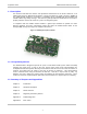
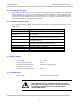
September 2001 S6350 Reader Reference Guide 1.1 Description This document describes the features and operational characteristics of the RI-STU-TRDC-01 & -02 S6350 High Frequency Multi-Protocol Readers. The RI-STU-TRDC-02 reader is shown in Figure 1. The S6350 Reader operates at a frequency of 13.56MHz and is compatible with both standard and ISO/IEC 15693 Tag-it inlays and tags.
Chapter 2 Hardware Description Topic Page 2.1 General Specification...................................................................................9 2.1.1 Functional Requirements........................................................................9 2.1.2 Power Supply ........................................................................................9 2.1.3 Output Power ........................................................................................9 2.1.4 Required Antenna Parameters..
September 2001 S6350 Reader Reference Guide 2.1 General Specification This chapter describes the electrical and mechanical specifications of the S6350 RI-STU-TRDC-02 reader. Operating at a frequency of 13.56 MHz, this low profile, low power device is designed to be easily integrated into many systems as an embedded device. All reader I/O is accomplished through the use of a 16-pin header connector (labeled as CN1), to include all communication, which is asynchronous RS232 as controlled by a host system.
September 2001 S6350 Reader Reference Guide 2.1.4 Required Antenna Parameters 50Ω ± 5Ω at 13.56 MHz 10 < Q < 30 Impedance Loaded Q Note: As no standard antenna is provided by Texas Instruments for the S6350 reader, the noted required antenna parameters must be closely followed by the integrator for the reader to operate properly. 2.1.
September 2001 S6350 Reader Reference Guide 2.1.6 Baseband receiver Minimum data pulse width 5uS Maximum data pulse width 500uS Typical settling time 50uS from the first transition Note: The receiver extracts the mean level of the incoming data stream as a reference. This takes approximately 50uS; therefore the data output of the receiver is not valid until after this time. 2.1.
September 2001 2.1.
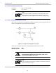
September 2001 S6350 Reader Reference Guide 2.1.10 RI-STU-TRDC-02 (CN1) Pin Assignments Figure 4: 16-pin Header Connector (CN1) viewed from component side.
September 2001 S6350 Reader Reference Guide 2.2 Mechanical Specifications 2.2.
September 2001 S6350 Reader Reference Guide 2.2.
Chapter 3 Reader Protocol Topic Page 3.1 Serial Protocol Definition ............................................................................ 17 3.1.1 Request Packet Format (Host to Reader).............................................. 17 3.1.2 Response Packet Format (Reader to Host)............................................ 18 3.1.3 Command Flags Request..................................................................... 18 3.1.4 Command Flags Response ............................................
September 2001 S6350 Reader Reference Guide 3.1 Serial Protocol Definition The S6350 reader accepts and sends data at RS232 levels, 57600 baud, 8 data bits, 1 start bit, 1 stop bit and no parity. The data packet from the host to the reader is known as the request and the reply from the reader to the host as the response. The host is always the primary station and initiates all communication sequences. These consist of request/response pairs where the host waits for a response before continuing.
September 2001 S6350 Reader Reference Guide 3.1.
September 2001 S6350 Reader Reference Guide 3.1.4 Command Flags Response The command flags in the response packet report the actions of the reader. The meanings of the bits are defined below. Bits 0-3 Reserved for future use. Bit 4 Error flag. If this flag is set the command was unsuccessful and the data section of the response packet contains the error code. (See section Appendix B for a list of error codes.) Bits 5-7 Reserved for future use. 3.1.
September 2001 S6350 Reader Reference Guide 3.2 Command Definitions 3.2.1 Tag-it™ HF Command Definitions Command Function (Tag-it HF) Read Single Non-addressed & Addressed Block Write Single Non-addressed & Addressed Block Lock Single Non-addressed & Addressed Block Read Transponder Details Special Read Block Command Command Code 02hex 03hex 04hex 05hex 0Fhex Read Block Command (02hex) TM Reads a single block of data from a Tag-it transponder.
September 2001 S6350 Reader Reference Guide Example Response packet 01 0A 00 00 00 00 03 00 08 F7hex Successful write. Lock Block Command (04hex) TM Locks a single block of data in a Tag-it transponder. If the address flag is set, the address forms the first part of the data section, followed by a single byte containing the number of the block to lock.
September 2001 S6350 Reader Reference Guide Example TM Read blocks 0, 3 & 4 of a Tag-it transponder (data byte = 00011001bin = 19hex ) Request packet 01 0A 00 00 00 00 0F 19 1D E2hex The data section of the response packet contains: The SID address (LSbyte first), Block 0 data (if selected) followed by a single byte indicating the lock status and then another single byte containing the block address, Block 1 data (if selected) followed by a single byte indicating the lock status and then another single byt
September 2001 S6350 Reader Reference Guide 3.2.2 Miscellaneous Commands Command Function Initiate FLASH Loader Command Send Data to FLASH Command Reader Version Command Read Inputs Command Write Reader Outputs Command RF Carrier on/off Command Command Code D0hex D8hex F0hex F1hex F2hex F4hex Initiate FLASH Loader Command (D0 hex) This command is used to initialize and transfer control to the FLASH loader software.
September 2001 S6350 Reader Reference Guide Reader Type Example Response packet 01 0C 00 00 00 00 F0 40 01 07 BB 44hex The version number is 1.4 The reader type response can be defined as follows: Type 07 = Indicates that the reader has been successfully loaded with the noted application firmware version number (in this example, version 1.4).
September 2001 S6350 Reader Reference Guide The response packet is similar to the request packet with the data section containing ‘00hex ’ for a successful write operation. Example Response packet 01 0A 00 00 00 00 F2 00 F9 06hex Write successful. RF Carrier on/off Command (F4hex) Switches the RF carrier on or off. The data section contains one byte FFhex to turn the carrier on or 00hex to turn the carrier off. Example Switch the carrier on.
September 2001 S6350 Reader Reference Guide 3.2.3 ISO/IEC FCD 15693 Part 3 Transmission Protocol TM In addition to supporting the Tag-it protocol outlined within the preceding section, the S6350 Mid-Range HF-I Reader complies with the standard RF interface and transmission protocol of ISO/IEC IS 15693-2 & 3. Please note that each of the ISO protocol command and response packets outlined within the following sections are contained within the standard reader protocol as outlined within Section 3.1.
September 2001 S6350 Reader Reference Guide The Configuration Byte (ISO Command Data Byte 0) As detailed in ISO/IEC 15693-2, the Configuration Byte (ISO Command Data Byte 0) is an 8bit byte that is used to configure the Data Coding Mode and Modulation Depth of the reader. Modulation Depth Bit 4 of the Configuration Byte is used to set Modulation Depth.
September 2001 S6350 Reader Reference Guide Request Packet Format Standard reader Request Packet Format (See Section 3.1) Header Packet Length Node Address Command Flag Command ‘01hex’ 1 byte LSB MSB 2 bytes LSB MSB 2 bytes Flags 1 byte ‘60hex’ 1 byte ISO Command Data Config.
September 2001 S6350 Reader Reference Guide Response Packet Format Standard reader Response Packet Format (See Section 3.
September 2001 S6350 Reader Reference Guide 3.2.3.3 Mandatory Commands The data packet from the host to the reader is known as the request and the reply from the reader to the host as the response. The host is always the primary station and initiates all communication sequences. These consist of request/response pairs where the host waits for a response before continuing. All ISO/IEC 15693-3 command request packets are contained within the standard reader command request packet format.
September 2001 S6350 Reader Reference Guide Valid Data & Collision Flags Valid Data Flags: This 16-bit field corresponds to whether valid data was received in the 16 possible Time Slots. Bits 0 to 7 of the LSB respectively correspond to Time Slots 1 to 8, while bits 0 to 7 of the MSB correspond to Time Slots 9 to 16 respectively. A set bit corresponds to valid data being received in that particular Time slot.
September 2001 S6350 Reader Reference Guide ISO Stay Quiet Request Command Packet: Command Code (02hex) Upon receipt of the Stay Quiet command, the ISO tag will enter the quiet state and will not initiate a response. Note: There is no response to the Stay Quiet command.
September 2001 S6350 Reader Reference Guide ISO Read Single Block Response Packet Header ‘01hex’ SOF Not Used Packet Length Node Address Response Flags Command 2 bytes 2 bytes 1 byte ‘60hex’ ISO Response Data Data Response when Error_flag is set Flags Error Code 1 byte 1 byte bytes 0-m Check sum 2 bytes CRC16 EOF Not Used Not Used CRC16 EOF Not Used Not Used OR SOF Not Used Response when Error_flag is not set Flags Block Security Data status 1 byte 1 byte 33 Block length
September 2001 S6350 Reader Reference Guide ISO Write Single Block: Command Code (21hex) ISO Write Single Block Request Command Packet Header ‘01hex’ Packet Length Node Address Cmd Flag Cmd 2 bytes 2 bytes 1 byte ‘60hex’ SOF *Flags Not Used 1 byte ISO Command Data Config.
September 2001 S6350 Reader Reference Guide ISO Lock Block: Command Code (22hex) ISO Lock Block Request Command Packet Header ‘01hex’ Packet Length Node Address Cmd Flag Cmd 2 bytes 2 bytes 1 byte ‘60hex’ SOF *Flags Not Used 1 byte ISO Command Data Config.
September 2001 S6350 Reader Reference Guide ISO Read Multiple Blocks: Command Code (23hex) ISO Read Multiple Blocks Request Command Packet Header ‘01hex’ Packet Length Node Address Cmd Flag Cmd 2 bytes 2 bytes 1 byte ‘60hex’ SOF Flags Not Used 1 byte ISO Command Data Config.
September 2001 S6350 Reader Reference Guide ISO Write AFI: Command Code (27hex) ISO Write AFI Request Command Packet Header ‘01hex’ Packet Length Node Address Cmd Flag Cmd 2 bytes 2 bytes 1 byte ‘60hex’ SOF *Flags Not Used 1 byte ISO Command Data Config.
September 2001 S6350 Reader Reference Guide ISO Lock AFI: Command Code (28hex) ISO Lock AFI Request Command Packet Header Packet Node Cmd Length Address Flag ‘01hex’ 2 bytes 2 bytes Cmd 1 byte ISO Command Data Config.
September 2001 S6350 Reader Reference Guide ISO Write DSFID: Command Code (29hex) ISO Write DSFID Request Command Packet Header ‘01hex’ Packet Length Node Address Cmd Flag Cmd 2 bytes 2 bytes 1 byte ‘60hex’ SOF *Flags Not Used 1 byte ISO Command Data Config.
September 2001 S6350 Reader Reference Guide ISO Lock DSFID: Command Code (2Ahex) ISO Lock DSFID Request Command Packet Header ‘01hex’ Packet Length Node Address Cmd Flag Cmd 2 bytes 2 bytes 1 byte ‘60hex’ SOF *Flags Not Used 1 byte ISO Command Data Config.
September 2001 S6350 Reader Reference Guide ISO Get Multiple Block Security Status: Command Code (2Chex) ISO Get Multiple Block Security Status Request Command Packet Header ‘01hex’ Packet Length Node Address Cmd Flag Cmd 2 bytes 2 bytes 1 byte ‘60hex’ SOF Flags Not Used 1 byte ISO Command Data Config.
Chapter 4 Regulatory and Warranty Notices Topic Page 4.1 FCC Conformity......................................................................................... 43 4.2 ETSI Conformity ........................................................................................ 43 4.3 CE Conformity........................................................................................... 43 4.4 Warranty and Liability ................................................................................
July 2001 Series 6350 Reader Reference Guide 4.1 FCC Conformity The S 6350 reader is an intentional radiator. The transmitter portion operates at 13.56 MHz and is subject to FCC Part 15, Subpart C, “Intentional Radiator,” paragraph 15.225 (13.55313.567MHz). Radiated emissions from the device are subject to the limits in Section 15.209 of the Rules outside of the 13.56 +/- 0.007 MHz band.
Appendix A Downloading Data to FLASH Memory The S 6350 Reader FLASH memory contains two areas: the application area for the Reader application firmware and a boot-loader area for the boot-loader firmware. The boot-loader memory is factory locked.
Appendix B Error Codes Code number 01hex 02hex 03hex 04hex 05hex 06hex 07hex 0Fhex Meaning Transponder not found Command not supported Packet BCC invalid Packet flags invalid for command General write failure Write failure due to locked block Transponder does not support function Undefined error 45