
Incor User's Guide power supply HPA070


SLUU186 − March 2004
10
TPS40055-Based Design Converts 12-V Bus to 1.8 V at 15 A (HPA070)
5 Test Setup
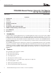
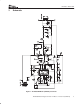
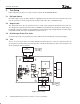
Figure 2 illustrates the basic test setup needed to evaluate the TPS40055EVM−001.
5.1 DC Input Source
The input voltage source should be capable of supplying between 10 V
DC
and 14 V
DC
and rated for at least 4
A of current. For best results the input leads should be made with a wire of 18AWG or larger.
5.2 Output Load
The output load can be either an electronic load or a resistive load configured to draw between 0 A and 15 A.
The output leads should be made with a wire of 16AWG or larger diameter wire. Monitor the output voltage on
the PCB by connecting a voltmeter to TP9 and TP10 to prevent voltage drops through PCB traces and the output
terminal block which can lead to substantial measurement errors.
5.3 Oscilloscope Probe Test Jacks
An oscilloscope probe test jack (TP8) has been included to allow monitoring the ourput voltage ripple.
5.4 Fan
There is no cover to prevent the user from probing the internal circuit nodes. There are components that can
get hot to the touch (above 60°C) in normal operation. A small fan delivering more than 15 cfm should be used
when operating at and near full load.
+
−
+−
Fan
V
IN
10 V to 14 V
V
IN
Test Points
TP1 = V
IN
(+)
TP2 = V
IN
(−)
V
OUT
Test Points
TP9 = V
OUT
(+)
TP10 = V
OUT
(−)
V
LOAD
1.8 V / 15 A
Figure 2. Test Setup