
Datasheet

www.ti.com
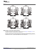
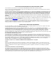
Figure 1. ISO7131, ISO7140, ISO7141, and ISO7142 Pinout
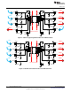
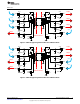
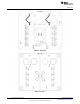
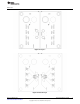
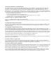
EVM Schematics of the Triple and Quad Isolators
This multifunctional EVM is designed with the signal paths displayed in Figure 2 throughFigure 5 for the
evaluation of the ISO7131, ISO7140, ISO7141 and ISO7142.
Note that each input channel has a 50-Ω load resistor to ground. Each output channel has a 4.7-pf load
capacitor to ground. These are not populated by default. Instead, there are pads on the board for the user
to install either a resistor or capacitor, depending on the desired configuration.
3
SLLU179–March 2013 ISO71xx EVM User’s Guide
Submit Documentation Feedback
Copyright © 2013, Texas Instruments Incorporated