
Datasheet

www.ti.com
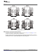
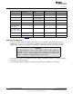
Table 1. Bill of Materials
Designator Value Description Package MFG
C1-C8 Not populated Capacitor 0805 Any
User selectable
(1)
C10, C13 1μF Power Supply 0603 Any
Decoupling Capacitors
C11, C14 0.1uF Power Supply 0402 Any
Decoupling Capacitors
C9, C12 10uF Power Supply 1206 Any
Decoupling Capacitors
U1 ISO7131CC Digital Isolator 16-DBQ TI
JMP1, JMP4, JMP5, 1 x 4 Jumper Jumper 0.1” Any
JMP8, JMP9, JMP12,
JMP15, JMP18
JMP2, JMP3, JMP6, 1 x 3 Jumper Jumper 0.1” Any
JMP7, JMP10, JMP11,
JMP13, JMP14, JMP16,
JMP17
R1-R8 Not populated Resistor 0805 Any
User selectable
(1)
TB1, TB2 2-pin female Terminal block 0.1” Any
(1)
Refer to the device datasheet (SLLSEF1) for allowable load values.
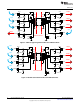
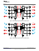
EVM Setup and Operation
The basic setup has two power supplies (TB1, TB2, P1-P4) to evaluate isolator performance with any
combination of 2.7 V, 3.3 V, or 5 V for VCC1 and VCC2. If both sides are to be evaluated at the same
supply voltage, only one power supply is required and can be used to power both sides of the EVM.
CAUTION
Note that although these devices provide galvanic isolation of up to 3000 Vrms,
this EVM cannot be used for isolation voltage testing. It is designed for the
evaluation of device operating parameters only and may be damaged if a
voltage exceeding 5.5 V is applied anywhere in the circuit.
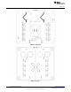
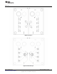
For the ISO7131, ISO7141, and ISO7142 isolators, JMP13 and JMP14 should be set to VCC1 and VCC2,
respectively, for normal operation.
For the ISO7140, JMP14 should be set to VCC2 for normal operation (JMP13 is not needed).
8
ISO71xx EVM User’s Guide SLLU179–March 2013
Submit Documentation Feedback
Copyright © 2013, Texas Instruments Incorporated