May ’00 Preface Series 2000 Reader System Micro-reader RI-STU-MRD1 Reference Guide 11-06-21-027 May 2000 1
Micro-reader - Reference Guide May ’00 Edition Three - May 2000 This is the third edition of this manual, it describes the following equipment: TIRIS Micro-reader Module RI-STU-MRD1 Texas Instruments (TI) reserves the right to make changes to its products or services or to discontinue any product or service at any time without notice. TI provides customer assistance in various technical areas, but does not have full access to data concerning the use and applications of customer's products.
PREFACE Read This First About This Guide This manual describes the TIRIS Micro-reader, its goal is to describe the reader, how it works, how to integrate it and how to use it. Conventions WARNING: A WARNING IS USED WHERE CARE MUST BE TAKEN, OR A CERTAIN PROCEDURE MUST BE FOLLOWED IN ORDER TO PREVENT INJURY OR HARM TO YOUR HEALTH.
Micro-reader - Reference Guide May ’00 Document Overview Page Chapter 1: Product Description. . . . . . . . . . . . . . . . . . . . . . . . . . . . . . . . . . . . . . 5 1.1 General............................................................................................... 6 1.2 Product Description ............................................................................ 6 1.3 Connector Pins...................................................................................
CHAPTER 1 Product Description Chapter 1: Product Description This chapter describes the hardware of the Micro-reader. It tells you about the module and how to integrate it. Topic Page 1.1 General..........................................................................................................6 1.2 Product Description.....................................................................................6 1.2.1 Power Supply ..........................................................................
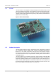
Micro-reader - Reference Guide 1.1 May ’00 General The Micro-reader is an intelligent module providing RF and Control functions to read and program TIRIS transponders. It is equipped with a Serial Communications Interface (SCI) which may be directly connected to commonly used system controllers. The Micro-reader works together with a 47 µHenry, low-Q antenna, and therefore the system does not need tuning. Figure 1: Micro-reader Module 1.
May ’00 1.2.1 Chapter 1. Product Description Power Supply There are two separate 5V supplies to the Micro-reader, one for the output stage (VSP) and the other for the logic (VSL). On power up VSL should rise faster than 0.1 V/ms to ensure a reliable operation. The Micro-reader has an on-board reset circuit which will reset it should the supply fall below 4 V (± 0.2 V).
Micro-reader - Reference Guide May ’00 Note: It is not recommended to have both wired and wireless synchronization switched on as synchronization could be unreliable. We recommend the use of bus drivers for wired synchronization with other Micro-readers and to prevent ESD damage. Wired or wireless synchronization prolongs the cycle time by typically 20 ms. 1.2.
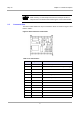
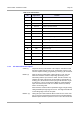
May ’00 Chapter 1. Product Description Note: While receiving a command protocol from the serial port Xon/Xoff is interpreted as normal data without affecting the serial communication. 1.3 Connector Pins The Micro-reader module has 30 pin connections which are shown in Figure 2 and listed in Table 1.
Micro-reader - Reference Guide May ’00 Table 1: Pin Connections 1.3.
May ’00 Chapter 1. Product Description processor takes between 28 ms and 132 ms (typically 72 ms) before it can receive new instructions via the serial communications interface. RXD (5) Input configured to receive serial data commands at 9600 Baud, 1 start bit, 8 data bits, no parity and 1 stop bit. TXD (6) Output configured to transmit serial data at 9600 Baud, 1 start bit, 8 data bits, no parity and 1 stop bit. GND (15, 25) Pins 15 and 25 are ground for the logic part.
Micro-reader - Reference Guide 1.3.
May ’00 Chapter 1.
CHAPTER 2 Communications Protocol Chapter 2: Communications Protocol This chapter describes the protocol that you need to use to send instructions from your PC to the micro-reader. It also describes the protocol that the micro-reader uses to respond to the PC. Topic Page 2.1 Protocol PC to Micro-reader .....................................................................15 2.1.1 Start Mark.............................................................................................15 2.1.2 Length ...
May ’00 2.1 Chapter 2. Communications Protocol Protocol PC to Micro-reader Start Length Cmd 1 Cmd 2 Byte 0 1 2 3 4(3) . . N+3(2) N+4(3) Data BCC Contents (hexadecimal value) Start Mark (SOH, 01hex) Length Command Field (1) Command Field (2) (optional) Data Field (1) Data Field (N) BCC Note: The total number of bytes sent within a protocol frame (including Start Mark and BCC) is limited to 41 bytes. Examples are given in section 5.1. 2.1.
Micro-reader - Reference Guide 2.1.3 May ’00 Command Field The 'Command Field(s)' defines the mode in which the Micro-reader operates and determines the operation that is to be carried out in the transponder. Depending on the setting of the relevant bits, the corresponding information specified in the Data Fields will be sent to the transponder or not. Thus all functions of each particular transponder type can be executed (see 2.1.4 for further information).
May ’00 Chapter 2. Communications Protocol Command Field (2) Command Field (2) is only present if bit 7 of Command Byte 1 is set. Bit 0 Use Special Write Timing Setting 1/0 1 2 Wireless Synchronization 1/0 DBCC calculation 1/0 Comment If set, needs to be determined in Data Field (see 2.1.
Micro-reader - Reference Guide 2.1.5 May ’00 BCC The 'BCC' field is a one-byte value of the Longitudinal Redundancy Check calculation (Xor'ed bytes) for the preceding message. The calculation is performed on the whole message excluding the Start-Mark. Example: 02 08 32 02 08 0000 0010 0000 1000 -------------------------------- XOR 0000 1010 32 0011 0010 -------------------------------- XOR 0011 1000 = 38 (hex) 2.2 Protocol Micro-reader to PC Start Length Status Byte 0 1 2 3 . . .
May ’00 2.2.3 Chapter 2. Communications Protocol Status The 'Status' byte provides feedback from the preceding read or program operation. Status Bits 0,1 2 3 4 5 6-7 2.2.4 Setting 00 (MSB,LSB) 01 10 11 1/0 1/0 1/0 1/0 Reserved Comment Transponder type: RO Transponder type: R/W Transponder type: MPT/SAMPT Other If set, Startbyte detected If set, DBCC O.K. If set, FBCC O.K.
CHAPTER 3 Specifications Chapter 3: Specifications This chapter provides the specifications for the micro-reader, its inputs and outputs, and its timing. Topic Page 3.1 Recommended Operating Conditions......................................................21 3.2 Timings .......................................................................................................22 3.3 Mechanical Data .........................................................................................
May ’00 3.1 Chapter 3. Specifications Recommended Operating Conditions Operating free-air temperature range T_oper -25 to +70 ºC Storage temperature range T_store -40 to +85 ºC Note: Free-air temperature: air temperature immediately surrounding the Module. If the module is incorporated into a housing, it must be guaranteed by proper design or cooling that the internal temperature does not exceed the absolute maximum ratings. Symbol Parameter Min. Typ. Max.
Micro-reader - Reference Guide 3.2 May ’00 Timings Parameter Typical Maxim Unit Read Cycle time without synch (no read) 100 105 ms 120 175 ms Read Cycle time without synch (valid read) 170 175 ms Read Cycle time with synch (valid read) 190 245 ms Interbyte time-out for serial communication 10*1 Read Cycle time with synch (no read) *1 3.3 ms If an Interbyte time-out occurs the Micro-reader performs a reset. Mechanical Data Parameter Minimum Typical Maximum Unit Length 37.
CHAPTER 4 Transponder Protocols Chapter 4: Transponder Protocols This chapter describes the protocols used when sending commands to the transponder and the protocols used by the transponder when responding. Topic Page 4.1 Transponder commands ...........................................................................24 4.1.1 Read RO, R/W .....................................................................................24 4.1.2 Program R/W ..........................................................
Micro-reader - Reference Guide 4.1 May ’00 Transponder commands This section describes the protocols that need to be sent by the PC to the transponder via the Micro-reader in order to execute the required function. 4.1.1 Read RO, R/W Figure 6: Read Function OFF RF TRANSMITTER POWER BURST READ 50 ms 20 ms ON 4.1.
May ’00 4.1.3.1 Chapter 4. Transponder Protocols General Read Page of MPT/SAMPT Figure 8: Data Format of the General Read Page Function 8 bit 128 bit O FF WRITE PO W ER BURST I R F T R A N S M ITT ER ADDRESS READ ON LSB 16 ms 50 ms 20 ms 86 ms 4.1.3.
Micro-reader - Reference Guide 4.1.3.4 May ’00 Selective Read Page of SAMPT Figure 11: Data Format of the Selective Read Page Function R F T RA NS MIT T ER 128 bit 32 - 56 b it 8 - 32 8 OFF PO W ER B UR S T I WRITE ADDRESS SELECTIVE ADDRESS 50 ms 16 ms 16 - 64 m s 16 WRITE FRAME BCC READ OR DISCHARGE ON 32 ms 20 ms LSB MSB 13 4 - 18 2 m s 4.1.3.
May ’00 4.2 Chapter 4. Transponder Protocols Transponder Responses This section shows the response telegrams of the current TIRIS transponder types. 4.2.1 Read Only Transponder Figure 14: RO Read Data Format START STOP R EAD D AT A PR E BIT S IDE N T IF IC AT IO N D AT A 8 16 DISCHARGE EN D BIT S D AT A B CC 64 16 16 8 112 bits 16 bits LSB 4.2.2 MSB Read/Write Transponder Figure 15: R/W Read Data Format START STOP READ DATA P RE BIT S ID EN T IF IC AT IO N D A TA 8 16 IDEN T .
Micro-reader - Reference Guide May ’00 *) If the status indicates 'Reserved', the read data cannot be interpreted as identification data. Note: It is strongly recommended to verify whether the requested function has actually been carried out in the transponder by checking the Read Address. If a 'not reliable' response message is received, the command must be sent again to guarantee transponder data retention.
CHAPTER 5 Communication Protocol Examples Chapter 5: Communication Protocol Examples This chapter provides some examples of some actual commands sent to a transponder and some possible responses. Topic Page 5.1 PC to Micro-reader .....................................................................................30 5.1.1 Read RO, R/W .....................................................................................30 5.1.2 Program R/W Transponder .................................................
Micro-reader - Reference Guide May ’00 5.1 PC to Micro-reader 5.1.1 Read RO, R/W Byte 5.1.
May ’00 5.1.3 Chapter 5. Communication Protocol Examples General Read Page of MPT The following sequence of bytes reads page 2 of an MPT. Byte 5.1.
Micro-reader - Reference Guide 5.1.6 May ’00 0 (hex) 01 Start Mark 1 05 Length 2 6C Command Field (1) 3 32 Data Field (1) Power Burst I with 50 ms duration (charge-up) 4 07 Data Field (2) Power Burst II with 15 ms duration (Progr.
May ’00 Chapter 5. Communication Protocol Examples 6 5.1.
Micro-reader - Reference Guide 5.2.2 4 58 Data Field (2) 5 4C -:- -:- 6 00 -:- -:- 7 00 -:- -:- 8 00 -:- -:- Identification Data 9 00 Data Field (7) Identification Data 10 00 Data Field (8) Identification Data (MSByte) 11 7B BCC BCC over previous bytes excluding Start Mark Successful Program Page 2 of MPT Byte 5.2.
APPENDIX A CE Declaration Appendix A: CE Declaration The Micro-reader module complies with the European CE requirements specified in the EMC Directive 89/336/EEC. The relevant documentation numbers are: Declaration of Conformity11-06-02-005 Type Examination Certificate11-06-05-001 If the Micro-reader is operated from a mains power supply, all power connections and additional components of the final device must comply with the European EMC directive.
APPENDIX B Demonstration Circuit Appendix B: Demonstration Circuit The Micro-reader module can be demonstrated using the circuit shown in Figure 17. Figure 17: Micro-reader Demonstration Circuit ANTENNA + DC IN L78M05CV 10 µF + 25V 10K 24 2 22 19 MICROREADER RDEN 0V 5 12 6 11 26 MAX232 25 1 14 240Ω 15 4 13 240Ω 21 2 1 30 27 16 3 29 CRDM WLSC 16 10 µF 25V + 5 15 6 240Ω 10K 0.
APPENDIX C Antenna Design Appendix C: Antenna Design C.1 Introduction This appendix gives an example of how you could construct an antenna to work with the micro-reader. It also provides information about calculating the Q factor and adapting the inductance range. The antenna properties should be: Q factor less than 20 Inductance between 46 and 48 µH Recommended maximum size 200 mm x 200 mm C.2 Antenna Construction Item List: Item Description Quantity 1 Enamelled solid copper wire, 0.2 mm 2.
Micro-reader - Reference Guide C.3 May ’00 Q Factor If the antenna’s Q factor exceeds 20: 1. The output capacitors will be overloaded and long term damage could result. 2. The antenna may still be resonating when the response from the transponder is received. Without built-in damping the data will not be correctly received. 3. The antenna may be detuned if there is any metal in the area.