
Datasheet

LM1085
SNVS038G –JULY 1999–REVISED MARCH 2013
www.ti.com
THERMAL CONSIDERATIONS FOR THE TO-220 PACKAGE
ICs heats up when in operation, and power consumption is one factor in how hot it gets. The other factor is how
well the heat is dissipated. Heat dissipation is predictable by knowing the thermal resistance between the IC and
ambient (θ
JA
). Thermal resistance has units of temperature per power (°C/W). The higher the thermal resistance,
the hotter the IC.
The LM1085 specifies the thermal resistance for the TO-220 package as Junction to Case (θ
JC
). In order to get
the total resistance to ambient (θ
JA
), two other thermal resistances must be added, one for case to heat-sink
(θ
CH
) and one for heatsink to ambient (θ
HA
). The junction temperature can be predicted as follows:
T
J
= T
A
+ (P
D
x (θ
JC
+ θ
CH
+ θ
HA
)) (1)
T
J
= T
A
+ (P
D
x θ
JA
) (2)
where T
J
is junction temperature, T
A
is ambient temperature, and P
D
is the power dissipation of the device.
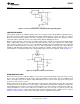
Device power dissipation is calculated as follows:
P
D
= OUTPUT Section Dissipation + CONTROL Section Dissipation (3)
P
D
= ( (V
IN
- V
OUT
) x I
LOAD
) + ( (V
IN
- V
OUT
) x I
GND
) (4)
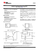
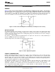
Figure 20 shows the voltages and currents which are present in the circuit.
Figure 20. Power Dissipation Diagram
Once the devices power is determined, the maximum allowable (θ
JA(max)
) is calculated as:
θ
JA(MAX)
= T
R(MAX)
/ P
D
(5)
θ
JA(MAX)
= T
J(MAX)
- T
A(MAX)
) / P
D
(6)
The required heat sink is determined by calculating its required thermal resistance (θ
HA(MAX)
).
θ
HA(MAX)
= θ
JA(MAX)
− (θ
JC
+ θ
CH
) (7)
If thermal compound is used, θ
CH
can be estimated at 0.2 C/W. If the case is soldered to the heat sink, then a
θ
CH
can be estimated as 0 C/W.
If PC board copper is going to be used as a heat sink, then Figure 21 can be used to determine the appropriate
area (size) of copper foil required.
10 Submit Documentation Feedback Copyright © 1999–2013, Texas Instruments Incorporated
Product Folder Links: LM1085