
Datasheet

LM1085
SNVS038G –JULY 1999–REVISED MARCH 2013
www.ti.com
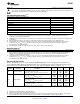
Electrical Characteristics (continued)
Limits in standard type are for T
J
= 25°C only; limits in boldface type apply over the operating junction temperature (T
J
)
range of -40°C to +125°C. Minimum and Maximum limits are ensured through test, design, or statistical correlation. Typical
values represent the most likely parametric norm at T
J
= 25°C, and are provided for reference purposes only.
Min Typ Max
Symbol Parameter Conditions Units
(1) (2) (1)
0.015 0.2
LM1085-ADJ, I
OUT
=10mA, 1.5V≤ (V
IN
-V
OUT
) ≤ 15V %
0.035 0.2
0.5 6
LM1085-3.3, I
OUT
= 0mA, 4.8V ≤ V
IN
≤ 15V mV
1.0 6
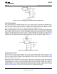
Line Regulation
ΔV
OUT
(4)
0.5 10
LM1085-5.0, I
OUT
= 0mA, 6.5V ≤ V
IN
≤ 20V mV
1.0 10
1.0 25
LM1085-12, I
OUT
=0mA, 13.5V ≤ V
IN
≤ 25V mV
2.0 25
LM1085-ADJ, (V
IN
-V
OUT
) = 3V, 10mA ≤ I
OUT
≤ I
FULL
0.1 0.3
%
LOAD
0.2 0.4
3 15
LM1085-3.3, V
IN
= 5V, 0 ≤ I
OUT
≤ I
FULL LOAD
mV
7 20
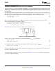
Load Regulation
ΔV
OUT
(4)
5 20
LM1085-5.0, V
IN
= 8V, 0 ≤ I
OUT
≤ I
FULL LOAD
mV
10 35
12 36
LM1085-12, V
IN
= 15V, 0 ≤ I
OUT
≤ I
FULL LOAD
mV
24 72
LM1085-ADJ, 3.3, 5, 12
V
DO
Dropout Voltage
(5)
V
ΔV
REF
, ΔV
OUT
= 1%, I
OUT
= 3A 1.3 1.5
LM1085-ADJ, V
IN
−V
OUT
= 5V 3.2 5.5
A
LM1085-ADJ, V
IN
−V
OUT
= 25V 0.2 0.5
I
LIMIT
Current Limit LM1085-3.3, V
IN
= 8.0V 3.2 5.5 A
LM1085-5.0, V
IN
= 10V 3.2 5.5 A
LM1085-12, V
IN
= 17V 3.2 5.5 A
Minimum Load
LM1085-ADJ, V
IN
−V
OUT
= 25V 5.0 10.0 mA
Current
(6)
LM1085-3.3, V
IN
≤ 18V 5.0 10.0 mA
I
GND
Quiescent Current LM1085-5.0, V
IN
≤ 20V 5.0 10.0 mA
LM1085-12, V
IN
≤ 25V 5.0 10.0 mA
Thermal Regulation T
A
= 25°C, 30ms Pulse .004 0.02 %/W
f
RIPPLE
= 120Hz, C
OUT
= 25µF Tantalum, I
OUT
= 3A
LM1085-ADJ
60 75 dB
C
ADJ
= 25µF, (V
IN
−V
O
) = 3V
Ripple Rejection
LM1085-3.3, V
IN
= 6.3V 60 72 dB
LM1085-5.0, V
IN
= 8.0V 60 68 dB
LM1085-12, V
IN
= 15V 54 60 dB
I
ADJ
Adjust Pin Current LM1085–ADJ 55 120 µA
Adjust Pin Current LM1085–ADJ
ΔI
ADJ
0.2 5 µA
Change 10mA ≤ I
OUT
≤ I
FULL LOAD
, 1.5V ≤ V
IN
−V
OUT
≤ 25V
Temperature Stability 0.5 %
Long Term Stability T
A
= 125°C, 1000 Hrs 0.3 1.0 %
RMS Output Noise
10Hz ≤ f ≤ 10 kHz 0.003 %
(% of V
OUT
)
3-Lead DDPAK/TO-263 - 0.7 -
Thermal Resistance
θ
JC
°C/W
(Junction-to-Case)
3-Lead TO-220 - 0.7 -
(4) Load and line regulation are measured at constant junction temperature, and are ensured up to the maximum power dissipation of 30W.
Power dissipation is determined by the input/output differential and the output current. Ensured maximum power dissipation will not be
available over the full input/output range.
(5) Dropout voltage is specified over the full output current range of the device.
(6) The minimum output current required to maintain regulation.
4 Submit Documentation Feedback Copyright © 1999–2013, Texas Instruments Incorporated
Product Folder Links: LM1085