
Datasheet

LM1085
www.ti.com
SNVS038G –JULY 1999–REVISED MARCH 2013
APPLICATION NOTE
GENERAL
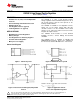
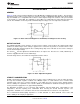
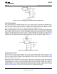
Figure 15 shows a basic functional diagram for the LM1085-Adj (excluding protection circuitry) . The topology is
basically that of the LM317 except for the pass transistor. Instead of a Darlingtion NPN with its two diode voltage
drop, the LM1085 uses a single NPN. This results in a lower dropout voltage. The structure of the pass transistor
is also known as a quasi LDO. The advantage a quasi LDO over a PNP LDO is its inherently lower quiescent
current. The LM1085 is ensured to provide a minimum dropout voltage 1.5V over temperature, at full load.
Figure 15. Basic Functional Diagram for the LM1085, excluding Protection circuitry
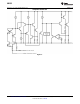
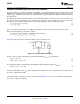
OUTPUT VOLTAGE
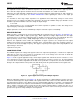
The LM1085 adjustable version develops at 1.25V reference voltage, (V
REF
), between the output and the adjust
terminal. As shown in figure 2, this voltage is applied across resistor R1 to generate a constant current I1. This
constant current then flows through R2. The resulting voltage drop across R2 adds to the reference voltage to
sets the desired output voltage.
The current I
ADJ
from the adjustment terminal introduces an output error . But since it is small (120uA max), it
becomes negligible when R1 is in the 100Ω range.
For fixed voltage devices, R1 and R2 are integrated inside the devices.
Figure 16. Basic Adjustable Regulator
STABILITY CONSIDERATION
Stability consideration primarily concern the phase response of the feedback loop. In order for stable operation,
the loop must maintain negative feedback. The LM1085 requires a certain amount series resistance with
capacitive loads. This series resistance introduces a zero within the loop to increase phase margin and thus
increase stability. The equivalent series resistance (ESR) of solid tantalum or aluminum electrolytic capacitors is
used to provide the appropriate zero (approximately 500 kHz).
The Aluminum electrolytic are less expensive than tantalums, but their ESR varies exponentially at cold
temperatures; therefore requiring close examination when choosing the desired transient response over
temperature. Tantalums are a convenient choice because their ESR varies less than 2:1 over temperature.
The recommended load/decoupling capacitance is a 10uF tantalum or a 50uF aluminum. These values will
assure stability for the majority of applications.
Copyright © 1999–2013, Texas Instruments Incorporated Submit Documentation Feedback 7
Product Folder Links: LM1085