
Datasheet

LM1949
www.ti.com
SNLS349C –FEB 1995–REVISED MARCH 2013
LM1949 Injector Drive Controller
Check for Samples: LM1949
1
FEATURES
DESCRIPTION
The LM1949 linear integrated circuit serves as an
2
• Low Voltage Supply (3V–5.5V)
excellent control of fuel injector drive circuitry in
• 22 mA Output Drive Current
modern automotive systems. The IC is designed to
• No RFI Radiation
control an external power NPN Darlington transistor
that drives the high current injector solenoid. The
• Adaptable to All Injector Current Levels
current required to open a solenoid is several times
• Highly Accurate Operation
greater than the current necessary to merely hold it
• TTL/CMOS Compatible Input Logic Levels
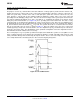
open; therefore, the LM1949, by directly sensing the
actual solenoid current, initially saturates the driver
• Short Circuit Protection
until the “peak” injector current is four times that of
• High Impedance Input
the idle or “holding” current (Figure 19–Figure 22).
• Externally Set Holding Current, I
H
This guarantees opening of the injector. The current
is then automatically reduced to the sufficient holding
• Internally Set Peak Current (4 × I
H
)
level for the duration of the input pulse. In this way,
• Externally Set Time-Out
the total power consumed by the system is
• Can be Modified for Full Switching Operation
dramatically reduced. Also, a higher degree of
• Available in Plastic 8-Pin PDIP
correlation of fuel to the input voltage pulse (or duty
cycle) is achieved, since opening and closing delays
of the solenoid will be reduced.
APPLICATIONS
Normally powered from a 5V ± 10% supply, the IC is
• Fuel Injection
typically operable over the entire temperature range
• Throttle Body Injection
(−55°C to +125°C ambient) with supplies as low as 3
• Solenoid Controls
volts. This is particularly useful under “cold crank”
• Air and Fluid Valves conditions when the battery voltage may drop low
enough to deregulate the 5-volt power supply.
• DC Motor Drives
The LM1949 is available in the plastic PDIP, (contact
factory for other package options).
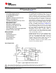
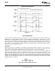
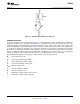
Typical Application
Figure 1. Typical Application and Test Circuit
1
Please be aware that an important notice concerning availability, standard warranty, and use in critical applications of
Texas Instruments semiconductor products and disclaimers thereto appears at the end of this data sheet.
2All trademarks are the property of their respective owners.
PRODUCTION DATA information is current as of publication date.
Copyright © 1995–2013, Texas Instruments Incorporated
Products conform to specifications per the terms of the Texas
Instruments standard warranty. Production processing does not
necessarily include testing of all parameters.