
Datasheet

LM231, LM331
www.ti.com
SNOSBI2B –JUNE 1999–REVISED MARCH 2013
LM231A/LM231/LM331A/LM331 Precision Voltage-to-Frequency Converters
Check for Samples: LM231, LM331
1
FEATURES
DESCRIPTION
The LM231/LM331 family of voltage-to-frequency
23
• Ensured Linearity 0.01% max
converters are ideally suited for use in simple low-
• Improved Performance in Existing Voltage-to-
cost circuits for analog-to-digital conversion, precision
Frequency Conversion Applications
frequency-to-voltage conversion, long-term
• Split or Single Supply Operation
integration, linear frequency modulation or
demodulation, and many other functions. The output
• Operates on Single 5V Supply
when used as a voltage-to-frequency converter is a
• Pulse Output Compatible with All Logic Forms
pulse train at a frequency precisely proportional to the
• Excellent Temperature Stability: ±50 ppm/°C
applied input voltage. Thus, it provides all the
max
inherent advantages of the voltage-to-frequency
conversion techniques, and is easy to apply in all
• Low Power Consumption: 15 mW Typical at 5V
standard voltage-to-frequency converter applications.
• Wide Dynamic Range, 100 dB min at 10 kHz
Further, the LM231A/LM331A attain a new high level
Full Scale Frequency
of accuracy versus temperature which could only be
• Wide Range of Full Scale Frequency: 1 Hz to attained with expensive voltage-to-frequency
modules. Additionally the LM231/331 are ideally
100 kHz
suited for use in digital systems at low power supply
• Low Cost
voltages and can provide low-cost analog-to-digital
conversion in microprocessor-controlled systems.
And, the frequency from a battery powered voltage-
to-frequency converter can be easily channeled
through a simple photo isolator to provide isolation
against high common mode levels.
The LM231/LM331 utilize a new temperature-
compensated band-gap reference circuit, to provide
excellent accuracy over the full operating temperature
range, at power supplies as low as 4.0V. The
precision timer circuit has low bias currents without
degrading the quick response necessary for 100 kHz
voltage-to-frequency conversion. And the output are
capable of driving 3 TTL loads, or a high voltage
output up to 40V, yet is short-circuit-proof against
V
CC
.
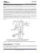
CONNECTION DIAGRAM
Figure 1. Plastic Dual-In-Line Package (PDIP)
See Package Number P (R-PDIP-T8)
1
Please be aware that an important notice concerning availability, standard warranty, and use in critical applications of
Texas Instruments semiconductor products and disclaimers thereto appears at the end of this data sheet.
2Teflon is a registered trademark of E.
3All other trademarks are the property of their respective owners.
PRODUCTION DATA information is current as of publication date.
Copyright © 1999–2013, Texas Instruments Incorporated
Products conform to specifications per the terms of the Texas
Instruments standard warranty. Production processing does not
necessarily include testing of all parameters.