
Datasheet

LM2594, LM2594HV
SNVS118C –DECEMBER 1999–REVISED APRIL 2013
www.ti.com
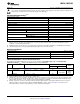
LM2594/LM2594HV-5.0 Electrical Characteristics
Specifications with standard type face are for T
J
= 25°C, and those with boldface type apply over full Operating
Temperature Range
Symbol Parameter Conditions LM2594/LM2594HV-5.0 Units
(Limits)
Typ
(1)
Limit
(2)
SYSTEM PARAMETERS
(3)
Test Circuit Figure 20
V
OUT
Output Voltage 7V ≤ V
IN
≤ V
INmax
, 0.1A ≤ I
LOAD
≤ 0.5A 5.0 V
4.800/4.750
V(min)
5.200/5.250
V(max)
η Efficiency V
IN
= 12V, I
LOAD
= 0.5A 82 %
(1) Typical numbers are at 25°C and represent the most likely norm.
(2) All limits ensured at room temperature (standard type face) and at temperature extremes (bold type face). All room temperature limits
are 100% production tested. All limits at temperature extremes are specified via correlation using standard Statistical Quality Control
(SQC) methods. All limits are used to calculate Average Outgoing Quality Level (AOQL).
(3) External components such as the catch diode, inductor, input and output capacitors, and voltage programming resistors can affect
switching regulator system performance. When the LM2594/LM2594HV is used as shown in the Figure 20 test circuit, system
performance will be as shown in system parameters section of Electrical Characteristics.
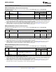
LM2594/LM2594HV-12 Electrical Characteristics
Specifications with standard type face are for T
J
= 25°C, and those with boldface type apply over full Operating
Temperature Range
Symbol Parameter Conditions LM2594/LM2594HV-12 Units
(Limits)
Typ
(1)
Limit
(2)
SYSTEM PARAMETERS
(3)
Test Circuit Figure 20
V
OUT
Output Voltage 15V ≤ V
IN
≤ V
INmax
, 0.1A ≤ I
LOAD
≤ 0.5A 12.0 V
11.52/11.40
V(min)
12.48/12.60
V(max)
η Efficiency V
IN
= 25V, I
LOAD
= 0.5A 88 %
(1) Typical numbers are at 25°C and represent the most likely norm.
(2) All limits ensured at room temperature (standard type face) and at temperature extremes (bold type face). All room temperature limits
are 100% production tested. All limits at temperature extremes are specified via correlation using standard Statistical Quality Control
(SQC) methods. All limits are used to calculate Average Outgoing Quality Level (AOQL).
(3) External components such as the catch diode, inductor, input and output capacitors, and voltage programming resistors can affect
switching regulator system performance. When the LM2594/LM2594HV is used as shown in the Figure 20 test circuit, system
performance will be as shown in system parameters section of Electrical Characteristics.
LM2594/LM2594HV-ADJ Electrical Characteristics
Specifications with standard type face are for T
J
= 25°C, and those with boldface type apply over full Operating
Temperature Range
Symbol Parameter Conditions LM2594/LM2594HV-ADJ Units
(Limits)
Typ
(1)
Limit
(2)
SYSTEM PARAMETERS
(3)
Test Circuit Figure 20
V
FB
Feedback Voltage 4.5V ≤ V
IN
≤ V
INmax
, 0.1A ≤ I
LOAD
≤ 0.5A 1.230 V
1.193/1.180
V
OUT
programmed for 3V. Circuit of Figure 20 V(min)
1.267/1.280
V(max)
η Efficiency V
IN
= 12V, I
LOAD
= 0.5A 80 %
(1) Typical numbers are at 25°C and represent the most likely norm.
(2) All limits ensured at room temperature (standard type face) and at temperature extremes (bold type face). All room temperature limits
are 100% production tested. All limits at temperature extremes are specified via correlation using standard Statistical Quality Control
(SQC) methods. All limits are used to calculate Average Outgoing Quality Level (AOQL).
(3) External components such as the catch diode, inductor, input and output capacitors, and voltage programming resistors can affect
switching regulator system performance. When the LM2594/LM2594HV is used as shown in the Figure 20 test circuit, system
performance will be as shown in system parameters section of Electrical Characteristics.
4 Submit Documentation Feedback Copyright © 1999–2013, Texas Instruments Incorporated
Product Folder Links: LM2594 LM2594HV