
Datasheet

LM2595
SNVS122B –MAY 1999–REVISED APRIL 2013
www.ti.com
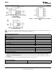
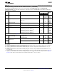
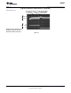
Test Circuit and Layout Guidelines
Fixed Output Voltage Versions
C
IN
—120 μF, 50V, Aluminum Electrolytic Nichicon “PL Series”
C
OUT
—120 μF, 25V Aluminum Electrolytic, Nichicon “PL Series”
D1—3A, 40V Schottky Rectifier, 1N5822
L1—100 μH, L29
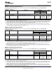
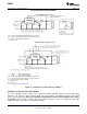
Adjustable Output Voltage Versions
C
IN
—120 μF, 50V, Aluminum Electrolytic Nichicon “PL Series”
C
OUT
—120 μF, 25V Aluminum Electrolytic, Nichicon “PL Series”
D1—3A, 40V Schottky Rectifier, 1N5822
L1—100 μH, L29
R
1
—1 kΩ, 1%
C
FF
—See Application Information Section
Figure 21. Standard Test Circuits and Layout Guides
Standard Test Circuits and Layout Guides
As in any switching regulator, layout is very important. Rapidly switching currents associated with wiring
inductance can generate voltage transients which can cause problems. For minimal inductance and ground
loops, the wires indicated by heavy lines should be wide printed circuit traces and should be kept as short
as possible. For best results, external components should be located as close to the switcher lC as possible
using ground plane construction or single point grounding.
10 Submit Documentation Feedback Copyright © 1999–2013, Texas Instruments Incorporated
Product Folder Links: LM2595