
Datasheet

20V
10V
0V
A
1A
0.5A
0A
B
50 mV
AC/
div.
C
LM2595
SNVS122B –MAY 1999–REVISED APRIL 2013
www.ti.com
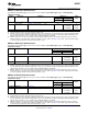
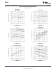
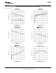
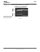
Typical Performance Characteristics (continued)
(Circuit of Figure 21)
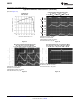
Continuous Mode Switching Waveforms
Feedback Pin V
IN
= 20V, V
OUT
= 5V, I
LOAD
= 1A
Bias Current L = 68 μH, C
OUT
= 120 μF, C
OUT
ESR = 100 mΩ
A: Output Pin Voltage, 10V/div.
B: Inductor Current 0.5A/div.
C: Output Ripple Voltage, 50 mV/div.
Horizontal Time Base: 2 µs/div.
Figure 16. Figure 17.
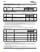
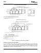
Discontinuous Mode Switching Waveforms Load Transient Response for Continuous Mode
V
IN
= 20V, V
OUT
= 5V, I
LOAD
= 600 mA V
IN
= 20V, V
OUT
= 5V, I
LOAD
= 250 mA to 750 mA
L = 22 μH, C
OUT
= 220 μF, C
OUT
ESR = 50 mΩ L = 68 μH, C
OUT
= 120 μF, C
OUT
ESR = 100 mΩ
A: Output Voltage, 100 mV/div. (AC)
B: 250 mA to 750 mA Load Pulse
Horizontal Time Base: 100 µs/div.
A: Output Pin Voltage, 10V/div.
B: Inductor Current 0.5A/div.
C: Output Ripple Voltage, 50 mV/div.
Horizontal Time Base: 2 µs/div.
Figure 18. Figure 19.
8 Submit Documentation Feedback Copyright © 1999–2013, Texas Instruments Incorporated
Product Folder Links: LM2595