
Datasheet

Operating the Evaluation Board
www.ti.com
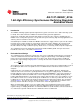
Figure 1. LM2651_EVAL Schematic for Adjustable Voltage
Table 1. Bill of Materials
Ref Designator Part Description Part Number
U1 IC LM2651MTC-ADJ LM2651MTC-ADJ
L1 Inductor Coilcraft DO3316P-223
CIN Tan Cap 100 µF 16V 10% Size = D Vishay 594D107X0016D2T
CSS Cer Cap 4.7 nF 50V X7R 10% 1206 Vishay VJ1206Y472KXAMB
CC2 Cer Cap 100 pF 50V NPO 1206 Vishay VJ1206A101JXAMB
CC1 Cer Cap 2.2 nF 50V X7R 10% 1206 Vishay VJ1206Y222KXAMB
COUT Tan Cap 120 µF 6.3V 10% Size = D Vishay 594D127X06R3C2T
CIN2 Cer Cap 0.1 µF 50V X7R 10% 0805 Vishay VJ0805Y104KXAMB
CB Cer Cap 0.1 µF 50V X7R 10% 0805 Vishay VJ0805Y104KXAMB
R1 Res 20.0 kΩ ⅛W 1% 0805 Vishay CRCW08052002F
R2 Res 19.6 kΩ ⅛W 1% 0805 Vishay CRCW08051962F
RC Res 30.0 kΩ ⅛W 5% 0805 Vishay CRCW0805303J
D1 Schottky Diode 1A SMA Motorola MBRA130LT3
3 Operating the Evaluation Board
3.1 Setup
The LM2651_EVAL evaluation board comes ready to be tested. The only setup needed is connecting the
input voltage to the V
IN
and GND posts. The load and output are connected to the V
OUT
post.
3.2 Operating Conditions
The input voltage to the LM2651 regulator must be within the range of 4V to 14V DC for proper operation.
The device will not function properly with voltages below 4V and damage may occur if any voltage greater
than 16V is applied. Refer to LM2651 1.5A High Efficiency Synchronous Switching Regulator (SNVS032)
for all performance characteristics.
2
AN-1147 LM2651_EVAL 1.5A High Efficiency Synchronous Switching SNVA019A–October 2007–Revised April 2013
Regulator Evaluation Board
Submit Documentation Feedback
Copyright © 2007–2013, Texas Instruments Incorporated