
Datasheet
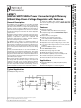
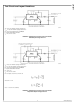

LM2671 Series Buck Regulator Design Procedure (Fixed Output)
PROCEDURE (Fixed Output Voltage Version) EXAMPLE (Fixed Output Voltage Version)
To simplify the buck regulator design procedure, National
Semiconductor is making available computer design software to be
used with the SIMPLE SWITCHER line of switching regulators.
LM267X Made Simple (version 6.0) is available on Windows
®
3.1,
NT, or 95 operating systems.
Given: Given:
V
OUT
= Regulated Output Voltage (3.3V, 5V, or 12V) V
OUT
= 5V
V
IN
(max) = Maximum DC Input Voltage V
IN
(max) = 12V
I
LOAD
(max) = Maximum Load Current I
LOAD
(max) = 500 mA
1. Inductor Selection (L1)
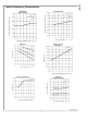
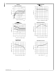
A. Select the correct inductor value selection guide from Figure 4
and Figure 5 or Figure 6 (output voltages of 3.3V, 5V, or 12V
respectively). For all other voltages, see the design procedure for
the adjustable version.
1. Inductor Selection (L1)
A. Use the inductor selection guide for the 5V version shown in
Figure 5.
B. From the inductor value selection guide, identify the inductance
region intersected by the Maximum Input Voltage line and the
Maximum Load Current line. Each region is identified by an
inductance value and an inductor code (LXX).
B. From the inductor value selection guide shown in Figure 5, the
inductance region intersected by the 12V horizontal line and the
500 mA vertical line is 47 μH, and the inductor code is L13.
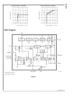
C. Select an appropriate inductor from the four manufacturer's part
numbers listed in Figure 8. Each manufacturer makes a different
style of inductor to allow flexibility in meeting various design
requirements. Listed below are some of the differentiating
characteristics of each manufacturer's inductors:
C. The inductance value required is 47 μH. From the table in Figure
8, go to the L13 line and choose an inductor part number from any
of the four manufacturers shown. (In most instances, both through
hole and surface mount inductors are available.)
Schott: ferrite EP core inductors; these have very low leakage
magnetic fields to reduce electro-magnetic interference (EMI) and
are the lowest power loss inductors
Renco: ferrite stick core inductors; benefits are typically lowest cost
inductors and can withstand E•T and transient peak currents above
rated value. Be aware that these inductors have an external
magnetic field which may generate more EMI than other types of
inductors.
Pulse: powered iron toroid core inductors; these can also be low
cost and can withstand larger than normal E•T and transient peak
currents. Toroid inductors have low EMI.
Coilcraft: ferrite drum core inductors; these are the smallest
physical size inductors, available only as SMT components. Be
aware that these inductors also generate EMI—but less than stick
inductors.
Complete specifications for these inductors are available from the
respective manufacturers. A table listing the manufacturers' phone
numbers is located in Figure 9.
2. Output Capacitor Selection (C
OUT
)
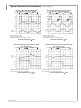
A. Select an output capacitor from the output capacitor table in
Figure 10. Using the output voltage and the inductance value found
in the inductor selection guide, step 1, locate the appropriate
capacitor value and voltage rating.
2. Output Capacitor Selection (C
OUT
)
A. Use the 5.0V section in the output capacitor table in Figure 10.
Choose a capacitor value and voltage rating from the line that
contains the inductance value of 47 μH. The capacitance and
voltage rating values corresponding to the 47 μH inductor are the:
www.national.com 10
LM2671