
Datasheet
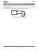


1.25A
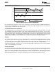
Load Current
Increases
I
PK
I
OCL
I
O
'I
Normal Operation
Current Limited
Inductor Current
LM2695
SNVS413A –JANUARY 2006–REVISED APRIL 2013
www.ti.com
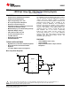
Figure 8. Inductor Current - Current Limit Operation
The current limit threshold can be increased by connecting an external resistor between SGND and ISEN. The
external resistor will typically be less than 1Ω. The peak current out of SW and ISEN must not exceed 2A. The
average current out of SW must be less than 1.5A.
N - Channel Buck Switch and Driver
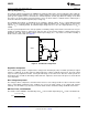
The LM2695 integrates an N-Channel buck switch and associated floating high voltage gate driver. The peak
current allowed through the buck switch is 2A, and the maximum allowed average current is 1.5A. The gate
driver circuit works in conjunction with an external bootstrap capacitor and an internal high voltage diode. A 0.022
µF capacitor (C4) connected between BST and SW provides the voltage to the driver during the on-time. During
each off-time, the SW pin is at approximately -1V, and C4 charges from V
CC
through the internal diode. The
minimum off-time of 250 ns ensures a minimum time each cycle to recharge the bootstrap capacitor.
Softstart
The softstart feature allows the converter to gradually reach a steady state operating point, thereby reducing
start-up stresses and current surges. Upon turn-on, after V
CC
reaches the under-voltage threshold, an internal
12.3 µA current source charges up the external capacitor at the SS pin to 2.5V. The ramping voltage at SS (and
the non-inverting input of the regulation comparator) ramps up the output voltage in a controlled manner.
An internal switch grounds the SS pin if V
CC
is below the under-voltage lockout threshold, if a thermal shutdown
occurs, or if the RON/SD pin is grounded.
Thermal Shutdown
The LM2695 should be operated so the junction temperature does not exceed 125°C. If the junction temperature
increases, an internal Thermal Shutdown circuit, which activates (typically) at 175°C, takes the controller to a low
power reset state by disabling the buck switch and the on-timer, and grounding the Softstart pin. This feature
helps prevent catastrophic failures from accidental device overheating. When the junction temperature reduces
below 155°C (typical hysteresis = 20°C), the Softstart pin is released and normal operation resumes.
10 Submit Documentation Feedback Copyright © 2006–2013, Texas Instruments Incorporated
Product Folder Links: LM2695