
Datasheet


t
ON
=
V
IN
1.3 x 10
-10
x
R
ON
FB
SW
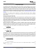
L1
C2
R1
R2
R3
LM2695
BST
VCC
D2
C3
C4
D1
ISEN
SGND
V
OUT1
LM2695
SNVS413A –JANUARY 2006–REVISED APRIL 2013
www.ti.com
Start-Up Regulator, V
CC
The start-up regulator is integral to the LM2695. The input pin (VIN) can be connected directly to line voltage up
to 30V, with transient capability to 33V. The V
CC
output regulates at 7.0V, and is current limited at 9.7 mA. Upon
power up, the regulator sources current into the external capacitor at VCC (C3). When the voltage on the VCC
pin reaches the under-voltage lockout threshold of 5.7V, the buck switch is enabled and the Softstart pin is
released to allow the Softstart capacitor (C6) to charge up.
The minimum input voltage is determined by the regulator’s dropout voltage, the V
CC
UVLO falling threshold
(≊5.5V), and the frequency. When V
CC
falls below the falling threshold the V
CC
UVLO activates to shut off the
output. If V
CC
is externally loaded, the minimum input voltage increases since the output impedance at V
CC
is
≊140Ω.
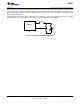
To reduce power dissipation in the start-up regulator, an auxiliary voltage can be diode connected to the V
CC
pin.
Setting the auxiliary voltage to between 8V and 14V shuts off the internal regulator, reducing internal power
dissipation. The sum of the auxiliary voltage and the input voltage (V
CC
+ V
IN
) cannot exceed 47V. Internally, a
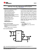
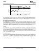
diode connects VCC to VIN. See Figure 6.
Figure 6. Self Biased Configuration
Regulation Comparator
The feedback voltage at FB is compared to the voltage at the Softstart pin (2.5V). In normal operation (the output
voltage is regulated), an on-time period is initiated when the voltage at FB falls below 2.5V. The buck switch
stays on for the programmed on-time, causing the FB voltage to rise above 2.5V. After the on-time period, the
buck switch stays off until the FB voltage falls below 2.5V. Input bias current at the FB pin is less than 100 nA
over temperature.
Over-Voltage Comparator
The voltage at FB is compared to an internal 2.9V reference. If the voltage at FB rises above 2.9V the on-time
pulse is immediately terminated. This condition can occur if the input voltage or the output load changes
suddenly, or if the inductor (L1) saturates. The buck switch remains off until the voltage at FB falls below 2.5V.
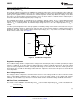
ON-Time Timer, and Shutdown
The on-time for the LM2695 is determined by the R
ON
resistor and the input voltage (V
IN
), and is calculated from:
(5)
8 Submit Documentation Feedback Copyright © 2006–2013, Texas Instruments Incorporated
Product Folder Links: LM2695