
Datasheet


STOP
RUN
RON/SD
Input
Voltage
LM2695
VIN
R
ON
t
ON(min)
=
V
OUT
x 288 ns
(V
IN(min)
- V
OUT
)
R
ON
=
V
OUT
F
S
x 1.3 x 10
-10
LM2695
www.ti.com
SNVS413A –JANUARY 2006–REVISED APRIL 2013
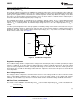
See Figure 4. The inverse relationship with V
IN
results in a nearly constant frequency as V
IN
is varied. To set a
specific continuous conduction mode switching frequency (FS), the R
ON
resistor is determined from the following:
(6)
In high frequency applicatons the minimum value for t
ON
is limited by the maximum duty cycle required for
regulation and the minimum off-time of (250 ns, ±15%). The minimum off-time limits the maximum duty cycle
achievable with a low voltage at V
IN
. The minimum allowed on-time to regulate the desired V
OUT
at the minimum
V
IN
is determined from the following:
(7)
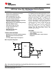
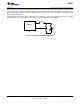
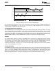
The LM2695 can be remotely shut down by taking the RON/SD pin below 0.8V. See Figure 7. In this mode the
SS pin is internally grounded, the on-timer is disabled, and bias currents are reduced. Releasing the RON/SD pin
allows normal operation to resume. The voltage at the RON/SD pin is between 1.5V and 3.0V, depending on V
IN
and the R
ON
resistor.
Figure 7. Shutdown Implementation
Current Limit
Current limit detection occurs during the off-time by monitoring the recirculating current through the free-wheeling
diode (D1). Referring to Typical Application Circuit and Block Diagram, when the buck switch is turned off the
inductor current flows through the load, into SGND, through the sense resistor, out of ISEN and through D1. If
that current exceeds 1.25A the current limit comparator output switches to delay the start of the next on-time
period if the voltage at FB is below 2.5V. The next on-time starts when the current out of ISEN is below 1.25A
and the voltage at FB is below 2.5V. If the overload condition persists causing the inductor current to exceed
1.25A during each on-time, that is detected at the beginning of each off-time. The operating frequency is lower
due to longer-than-normal off-times.
Figure 8 illustrates the inductor current waveform. During normal operation the load current is Io, the average of
the ripple waveform. When the load resistance decreases the current ratchets up until the lower peak reaches
1.25A. During the Current Limited portion of Figure 8, the current ramps down to 1.25A during each off-time,
initiating the next on-time (assuming the voltage at FB is <2.5V). During each on-time the current ramps up an
amount equal to:
ΔI = (V
IN
- V
OUT
) x t
ON
/ L1 (8)
During this time the LM2695 is in a constant current mode, with an average load current (I
OCL
) equal to 1.25A +
ΔI/2.
Copyright © 2006–2013, Texas Instruments Incorporated Submit Documentation Feedback 9
Product Folder Links: LM2695