
Datasheet

LM2742
HG
BOOT
I
SEN
LG
PGND
FB
V
CC
SD
PWGD
FREQ
SS
SGND
EAO
PGND
+5V
V
IN
= 3.3V
V
O
= 1.2V@5A
C
O
1,2
2200 PF
6.3V, 2.8A
1.5 PH
6.1A, 9.6 m:
R
fb2
C
C2
R
C1
R
CS
C
SS
R
FADJ
R
IN
C
IN
D1
C
BOOT
Q1
Q2
10 PF
6.3V
10k
2.2k
10k
392k
2.2p
180p
12n
63.4k
2.2 PF
10:
0.1P
C
IN
1,2
L1
+
C
C1
R
fb1
Si4884DY
Si4884DY
LM2742
www.ti.com
SNVS266C –MARCH 2004–REVISED MARCH 2013
LM2742 N-Channel FET Synchronous Buck Regulator Controller for Low Output Voltages
Check for Samples: LM2742
1
FEATURES
DESCRIPTION
The LM2742 is a high-speed, synchronous, switching
2
• Input Power from 1V to 16V
regulator controller. It is intended to control currents
• Output Voltage Adjustable down to 0.6V
of 0.7A to 20A with up to 95% conversion efficiencies.
• Power Good Flag, Adjustable Soft-start and
Power up and down sequencing is achieved with the
Output Enable for Easy Power Sequencing
power-good flag, adjustable soft-start and output
enable features. The LM2742 operates from a low-
• Reference Accuracy: 1.5% (0°C–125°C)
current 5V bias and can convert from a 1V to 16V
• Current Limit Without Sense Resistor
power rail. The part utilizes a fixed-frequency,
• Soft Start
voltage-mode, PWM control architecture and the
switching frequency is adjustable from 50kHz to
• Switching Frequency from 50 kHz to 2 MHz
2MHz by setting the value of an external resistor.
• 40ns Typical Minimum On-time
Current limit is achieved by monitoring the voltage
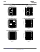
• TSSOP-14 Package
drop across the on-resistance of the low-side
MOSFET, which enables on-times on the order of
APPLICATIONS 40ns, one of the best in the industry. The wide range
of operating frequencies gives the power supply
• POL Power Supply Modules
designer the flexibility to fine-tune component size,
• Cable Modems
cost, noise and efficiency. The adaptive, non-
overlapping MOSFET gate-drivers and high-side
• Set-Top Boxes/ Home Gateways
bootstrap structure helps to further maximize
• DDR Core Power
efficiency. The high-side power FET drain voltage can
• High-Efficiency Distributed Power
be from 1V to 16V and the output voltage is
adjustable down to 0.6V.
• Local Regulation of Core Power
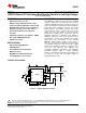
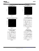
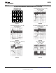
TYPICAL APPLICATION
Figure 1. Typical Application Circuit
1
Please be aware that an important notice concerning availability, standard warranty, and use in critical applications of
Texas Instruments semiconductor products and disclaimers thereto appears at the end of this data sheet.
2All trademarks are the property of their respective owners.
PRODUCTION DATA information is current as of publication date.
Copyright © 2004–2013, Texas Instruments Incorporated
Products conform to specifications per the terms of the Texas
Instruments standard warranty. Production processing does not
necessarily include testing of all parameters.