
Datasheet

LM2931-N
SNOSBE5G –MARCH 2000–REVISED APRIL 2013
www.ti.com
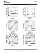
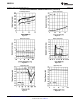
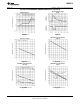
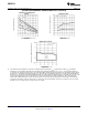
TYPICAL PERFORMANCE CHARACTERISTICS (continued)
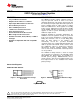
Maximum Power Dissipation
(TO-263)
(1)
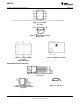
On/Off Threshold
Figure 32. Figure 33.
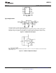
Output Capacitor ESR
Figure 34.
(1) The maximum power dissipation is a function of maximum junction temperature T
Jmax
, total thermal resistance θ
JA
, and ambient
temperature T
A
. The maximum allowable power dissipation at any ambient temperature is P
D
= (T
Jmax
− T
A
)/θ
JA
. If this dissipation is
exceeded, the die temperature will rise above 150°C and the LM2931-N will go into thermal shutdown. For the LM2931-N in the TO-92
package, θ
JA
is 195°C/W; in the SOIC-8 package, θ
JA
is 160°C/W, and in the TO-220 package, θ
JA
is 50°C/W; in the DDPAK/TO-263
package, θ
JA
is 73°C/W; and in the 6-Bump DSBGA package θ
JA
is 290°C/W. If the TO-220 package is used with a heat sink, θ
JA
is the
sum of the package thermal resistance junction-to-case of 3°C/W and the thermal resistance added by the heat sink and thermal
interface.If the TO-263 package is used, the thermal resistance can be reduced by increasing the P.C. board copper area thermally
connected to the package: Using 0.5 square inches of copper area, θ
JA
is 50°C/W; with 1 square inch of copper area, θ
JA
is 37°C/W;
and with 1.6 or more square inches of copper area, θ
JA
is 32°C/W.
10 Submit Documentation Feedback Copyright © 2000–2013, Texas Instruments Incorporated
Product Folder Links: LM2931-N