
Datasheet

LM2940-N, LM2940C
www.ti.com
SNVS769I –MARCH 2000–REVISED APRIL 2013
LM2940-N/LM2940C 1A Low Dropout Regulator
Check for Samples: LM2940-N, LM2940C
1
FEATURES
DESCRIPTION
The LM2940-N/LM2940C positive voltage regulator
2
• Dropout Voltage Typically 0.5V @I
O
= 1A
features the ability to source 1A of output current with
• Output Current in Excess of 1A
a dropout voltage of typically 0.5V and a maximum of
• Output Voltage Trimmed Before Assembly
1V over the entire temperature range. Furthermore, a
quiescent current reduction circuit has been included
• Reverse Battery Protection
which reduces the ground current when the
• Internal Short Circuit Current Limit
differential between the input voltage and the output
• Mirror Image Insertion Protection
voltage exceeds approximately 3V. The quiescent
current with 1A of output current and an input-output
• P
+
Product Enhancement Tested
differential of 5V is therefore only 30 mA. Higher
quiescent currents only exist when the regulator is in
the dropout mode (V
IN
− V
OUT
≤ 3V).
Designed also for vehicular applications, the LM2940-
N/LM2940C and all regulated circuitry are protected
from reverse battery installations or 2-battery jumps.
During line transients, such as load dump when the
input voltage can momentarily exceed the specified
maximum operating voltage, the regulator will
automatically shut down to protect both the internal
circuits and the load. The LM2940/LM2940C cannot
be harmed by temporary mirror-image insertion.
Familiar regulator features such as short circuit and
thermal overload protection are also provided.
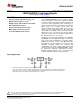
Typical Application
*Required if regulator is located far from power supply filter.
**C
OUT
must be at least 22 μF to maintain stability. May be increased without bound to maintain regulation during
transients. Locate as close as possible to the regulator. This capacitor must be rated over the same operating
temperature range as the regulator and the ESR is critical; see curve.
1
Please be aware that an important notice concerning availability, standard warranty, and use in critical applications of
Texas Instruments semiconductor products and disclaimers thereto appears at the end of this data sheet.
2All trademarks are the property of their respective owners.
PRODUCTION DATA information is current as of publication date.
Copyright © 2000–2013, Texas Instruments Incorporated
Products conform to specifications per the terms of the Texas
Instruments standard warranty. Production processing does not
necessarily include testing of all parameters.