
Datasheet
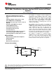

FB
EN
VIN
VCON
SW
V
IN
2.7V to 5.5V
V
OUT
0.6V to 3.4V
10 PF
4.7 PF
GND
0.47 PH
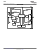
LM3241
V
OUT
= 2.5 x VCON
LM3241
www.ti.com
SNOSB38B –JANUARY 2009–REVISED APRIL 2013
LM3241 6MHz, 750mA Miniature, Adjustable, Step-Down DC-DC Converter for RF Power
Amplifiers
Check for Samples: LM3241
1
FEATURES
DESCRIPTION
The LM3241 is a DC-DC converter optimized for
2
• 6MHz (typ.) PWM Switching Frequency
powering RF power amplifiers (PAs) from a single
• Operates from a Single Li-Ion Cell (2.7V to
Lithium-Ion cell; however, it may be used in many
5.5V)
other applications. It steps down an input voltage
• Adjustable Output Voltage (0.6V to 3.4V)
from 2.7V to 5.5V to an adjustable output voltage
from 0.6V to 3.4V. Output voltage is set using a
• 750 mA Maximum Load Capability
VCON analog input for controlling power levels and
• High Efficiency (95% typ. at 3.9V
IN
, 3.3V
OUT
at
efficiency of the RF PA.
500 mA)
The LM3241 offers three modes of operation. In
• Automatic ECO/PWM mode change
PWM mode the device operates at a fixed frequency
• 6-bump DSBGA Package
of 6MHz (typ.) which minimizes RF interference when
driving medium-to-heavy loads. At light load, the
• Current Overload Protection
device enters into ECO mode automatically and
• Thermal Overload Protection
operates with reduced switching frequency. In ECO
• Soft Start Function
mode, the quiescent current is reduced and extends
• C
IN
and C
OUT
are 0402 (1005) case size and
the battery life. Shutdown mode turns the device off
and reduces battery consumption to 0.1 µA (typ.).
6.3V of rated-voltage ceramic capacitor
• Small Chip Inductor in 0805 (2012) case size
The LM3241 is available in a 6-bump lead-free
DSBGA package. A high-switching frequency (6MHz)
allows use of tiny surface-mount components. Only
APPLICATIONS
three small external surface-mount components, an
• Battery-Powered 3G/4G Power Amplifiers
inductor and two ceramic capacitors are required.
• Hand-Held Radios
• RF PC Cards
• Battery-Powered RF Devices
TYPICAL APPLICATION
1
Please be aware that an important notice concerning availability, standard warranty, and use in critical applications of
Texas Instruments semiconductor products and disclaimers thereto appears at the end of this data sheet.
2All trademarks are the property of their respective owners.
PRODUCTION DATA information is current as of publication date.
Copyright © 2009–2013, Texas Instruments Incorporated
Products conform to specifications per the terms of the Texas
Instruments standard warranty. Production processing does not
necessarily include testing of all parameters.