
Datasheet

R
T
C
T
V
SW
LM3429
RCT
Start t
ON
V
IN
/25
Reset timer
LM3429, LM3429-Q1
SNVS616G –APRIL 2009–REVISED MAY 2013
www.ti.com
Even though the off-time control is quasi-hysteretic, the input voltage proportionality in the off-timer creates an
essentially constant switching frequency over the entire operating range for boost and buck-boost topologies.
The buck topology can be designed to give constant ripple over either input voltage or output voltage, however
switching frequency is only constant at a specific operating point .
This type of control minimizes the control loop compensation necessary in many switching regulators, simplifying
the design process. The averaging mechanism in the peak detection control loop provides extremely accurate
LED current regulation over the entire operating range.
PRO control was designed to mitigate “current mode instability” (also called “sub-harmonic oscillation”) found in
standard peak current mode control when operating near or above 50% duty cycles. When using standard peak
current mode control with a fixed switching frequency, this condition is present, regardless of the topology.
However, using a constant off-time approach, current mode instability cannot occur, enabling easier design and
control.
Predictive off-time advantages:
• There is no current mode instability at any duty cycle.
• Higher duty cycles / voltage transformation ratios are possible, especially in the boost regulator.
The only disadvantage is that synchronization to an external reference frequency is generally not available.
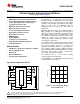
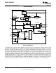
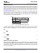
SWITCHING FREQUENCY
An external resistor (R
T
) connected between the RCT pin and the switch node (where D1, Q1, and L1 connect),
in combination with a capacitor (C
T
) between the RCT and AGND pins, sets the off-time (t
OFF
) as shown in
Figure 15. For boost and buck-boost topologies, the V
IN
proportionality ensures a virtually constant switching
frequency (f
SW
).
Figure 15. Off-timer Circuitry for Boost and Buck-boost Regulators
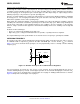
For a buck topology, R
T
and C
T
are also used to set t
OFF
, however the V
IN
proportionality will not ensure a
constant switching frequency. Instead, constant ripple operation can be achieved. Changing the connection of R
T
in Figure 15 from V
SW
to V
IN
will provide a constant ripple over varying V
IN
. Adding a PNP transistor as shown in
Figure 16 will provide constant ripple over varying V
O
.
10 Submit Documentation Feedback Copyright © 2009–2013, Texas Instruments Incorporated
Product Folder Links: LM3429 LM3429-Q1