
Datasheet

2OVHYSO
RA20V xP=
¸
¸
¹
·
¨
¨
©
§
x
=
-OFFTURN
24V.1V
x
+
OV1
OV2
R5.0
R
1OV
R
1
¸
¸
¹
·
¨
¨
©
§
x
=
-OFFTURN
24V.1V
1OV
R
+
2OVOV
RR
LM3429
OVP
R
OV2
R
OV1
LED+
LED-
LM3429, LM3429-Q1
www.ti.com
SNVS616G –APRIL 2009–REVISED MAY 2013
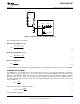
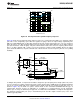
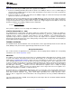
The LM3429 can be configured to detect an output (or input) over-voltage condition via the OVP pin. The pin
features a precision 1.24V threshold with 20 µA (typical) of hysteresis current as shown in Figure 23. When the
OVLO threshold is exceeded, the GATE pin is immediately pulled low and a 20 µA current source provides
hysteresis to the lower threshold of the OVLO hysteretic band.
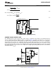
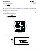
If the LEDs are referenced to a potential other than ground (floating), as in the buck-boost and buck
configuration, the output voltage (V
O
) should be sensed and translated to ground by using a single PNP as
shown in Figure 24.
Figure 24. Floating Output OVP Circuitry
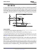
The over-voltage turn-off threshold (V
TURN-OFF
) is defined as follows:
Ground Referenced
(20)
Floating
(21)
In the ground referenced configuration, the voltage across R
OV2
is V
O
- 1.24V whereas in the floating
configuration it is V
O
- 620 mV where 620 mV approximates the V
BE
of the PNP transistor.
The over-voltage hysteresis (V
HYSO
) is defined as follows:
(22)
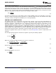
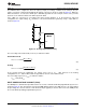
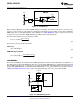
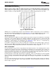
INPUT UNDER-VOLTAGE LOCKOUT (UVLO)
The nDIM pin is a dual-function input that features an accurate 1.24V threshold with programmable hysteresis as
shown in Figure 25. This pin functions as both the PWM dimming input for the LEDs and as a V
IN
UVLO. When
the pin voltage rises and exceeds the 1.24V threshold, 20 µA (typical) of current is driven out of the nDIM pin into
the resistor divider providing programmable hysteresis.
Copyright © 2009–2013, Texas Instruments Incorporated Submit Documentation Feedback 17
Product Folder Links: LM3429 LM3429-Q1