
Datasheet


D
=
INO
VV
+
O
V
D =
INO
VV -
O
V
D =
O
V
IN
V
r
D
= N x r
LED
V
O
= N x V
LED
LM3429, LM3429-Q1
SNVS616G –APRIL 2009–REVISED MAY 2013
www.ti.com
Design Guide
Refer to Basic Topology Schematics section.
SPECIFICATIONS
Number of series LEDs: N
Single LED forward voltage: V
LED
Single LED dynamic resistance: r
LED
Nominal input voltage: V
IN
Input voltage range: V
IN-MAX
, V
IN-MIN
Switching frequency: f
SW
Current sense voltage: V
SNS
Average LED current: I
LED
Inductor current ripple: Δi
L-PP
LED current ripple: Δi
LED-PP
Peak current limit: I
LIM
Input voltage ripple: Δv
IN-PP
Output OVLO characteristics: V
TURN-OFF
, V
HYSO
Input UVLO characteristics: V
TURN-ON
, V
HYS
1. OPERATING POINT
Given the number of series LEDs (N), the forward voltage (V
LED
) and dynamic resistance (r
LED
) for a single LED,
solve for the nominal output voltage (V
O
) and the nominal LED string dynamic resistance (r
D
):
(27)
(28)
Solve for the ideal nominal duty cycle (D):
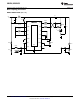
Buck
(29)
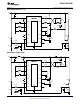
Boost
(30)
Buck-boost
(31)
Using the same equations, find the minimum duty cycle (D
MIN
) using maximum input voltage (V
IN-MAX
) and the
maximum duty cycle (D
MAX
) using the minimum input voltage (V
IN-MIN
). Also, remember that D' = 1 - D.
2. SWITCHING FREQUENCY
Set the switching frequency (f
SW
) by assuming a C
T
value of 1 nF and solving for R
T
:
24 Submit Documentation Feedback Copyright © 2009–2013, Texas Instruments Incorporated
Product Folder Links: LM3429 LM3429-Q1