
Datasheet

mW82m50A28.1RIP
2
DSON
2
RMSTT
=
:x
=
x
=
-
x
I
RMST
=
-
I
LED
D
c
=
x
A28.1
=
0.467
A1
533.0
D
=
A2.1A1
=
x
677.01-
677.0
I
MAXT-
V91V21V70VVV
OMAXINMAXT
=+=+=
--
C
IN
= 3 x 4.7 PF
x
A1
=
I
LED
I
RMSIN-
=
1- 0.677
677.0
1.45A
x
1- D
MAX
D
MAX
=
C
IN
==
kHz700mV100 x
467.0A1 x
F66.6 P=
f
'v
SWPPIN-
x
DI
LED
x
F1.0C
FS
P=
F0.22C
COMP
P=
:10R
FS
=
1
= F091.0
1
P==C
FS
10:
x
sec
rad
M1.1
10:
3P
Zx
1010max
1P
xZ
=
x
=
,
1Z1P
ZZ
sec
rad
k110
=
sec
rad
M1.110
=
x
3P
Z
3P
Z
F17.0
1
1
C
CMP
P===
173.1
e5
sec
rad
6
x :
e5
6
2P
xZ
:
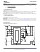
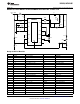
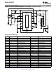
LM3429, LM3429-Q1
www.ti.com
SNVS616G –APRIL 2009–REVISED MAY 2013
Solve for C
CMP
:
(116)
To attenuate switching noise, calculate ω
P3
:
(117)
Assume R
FS
= 10Ω and solve for C
FS
:
(118)
The chosen components from step 7 are:
(119)
8. INPUT CAPACITANCE
Solve for the minimum C
IN
:
(120)
To minimize power supply interaction a 200% larger capacitance of approximately 14 µF is used, therefore the
actual Δv
IN-PP
is much lower. Since high voltage ceramic capacitor selection is limited, three 4.7 µF X7R
capacitors are chosen.
Determine minimum allowable RMS current rating:
(121)
The chosen components from step 8 are:
(122)
9. NFET
Determine minimum Q1 voltage rating and current rating:
(123)
(124)
A 100V NFET is chosen with a current rating of 32A due to the low R
DS-ON
= 50 mΩ. Determine I
T-RMS
and P
T
:
(125)
(126)
Copyright © 2009–2013, Texas Instruments Incorporated Submit Documentation Feedback 35
Product Folder Links: LM3429 LM3429-Q1