
Datasheet


= D =
t
ON
t
ON
+ t
OFF
= t
ON
x f
SW
V
O
V
IN
L2
R3
C11
Q2
Q3
D10
I
COLL
4
6
7
8
R4
PGN
D
ISNS
GAT
E
COFF
LM3444
V
BUCK
C12
LM3444
www.ti.com
SNVS682C –NOVEMBER 2010–REVISED MAY 2013
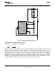
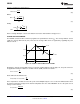
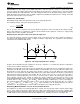
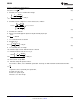
Figure 15. LM3444 Buck Regulation Circuit
OVERVIEW OF CONSTANT OFF-TIME CONTROL
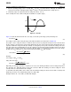
A buck converter’s conversion ratio is defined as:
(3)
Constant off-time control architecture operates by simply defining the off-time and allowing the on-time, and
therefore the switching frequency, to vary as either V
IN
or V
O
changes. The output voltage is equal to the LED
string voltage (V
LED
), and should not change significantly for a given application. The input voltage or V
BUCK
in
this analysis will vary as the input line varies. The length of the on-time is determined by the sensed inductor
current through a resistor to a voltage reference at a comparator. During the on-time, denoted by t
ON
, MOSFET
switch Q2 is on causing the inductor current to increase. During the on-time, current flows from V
BUCK
, through
the LEDs, through L2, Q2, and finally through R3 to ground. At some point in time, the inductor current reaches a
maximum (I
L2-PK
) determined by the voltage sensed at R3 and the ISNS pin. This sensed voltage across R3 is
compared against the voltage of FILTER, at which point Q2 is turned off by the controller.
Copyright © 2010–2013, Texas Instruments Incorporated Submit Documentation Feedback 11
Product Folder Links: LM3444