
Datasheet


V
BUCK(MAX)
= V
AC-RMS(MAX)
x
2
V
LED(MIN)
t
ON(MIN)
=
V
BUCK(MAX)
f
SW
1
K
1
u
V
BUCK
(V)
NORMALIZED SW FREQ
1.50
1.25
1.00
0.75
0.50
0.25
0 50 100 150 200
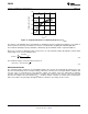
3 LEDs
5 LEDs
7 LEDs
9 LEDs
Series
connected LEDs
LM3444
SNVS682C –NOVEMBER 2010–REVISED MAY 2013
www.ti.com
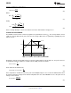
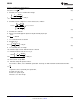
Figure 17. Graphical Illustration of Switching Frequency vs V
BUCK
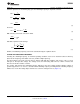
The off-time of the LM3444 can be programmed for switching frequencies ranging from 30 kHz to over 1 MHz. A
trade-off between efficiency and solution size must be considered when designing the LM3444 application.
The maximum switching frequency attainable is limited only by the minimum on-time requirement (200 ns).
Worst case scenario for minimum on time is when V
BUCK
is at its maximum voltage (AC high line) and the LED
string voltage (V
LED
) is at its minimum value.
(12)
The maximum voltage seen by the Buck Converter is:
(13)
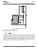
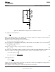
INDUCTOR SELECTION
The controlled off-time architecture of the LM3444 regulates the average current through the inductor (L2), and
therefore the LED string current. The input voltage to the buck converter (V
BUCK
) changes with line variations and
over the course of each half-cycle of the input line voltage. The voltage across the LED string is relatively
constant, and therefore the current through R4 is constant. This current sets the off-time of the converter and
therefore the output volt-second product (V
LED
x off-time) remains constant. A constant volt-second product
makes it possible to keep the ripple through the inductor constant as the voltage at V
BUCK
varies.
14 Submit Documentation Feedback Copyright © 2010–2013, Texas Instruments Incorporated
Product Folder Links: LM3444