
Datasheet


'i #
t
OFF
x
V
LED
L2
V
L(OFF-TIME)
= V
LED
= L x
'i
't
V
L(OFF-TIME)
= V
LED
= L x
(I
(MAX)
- I
(MIN)
)
't
di
Q = L
dt
-
C12
R3
Q2
-
D10
V
LED
V
BUCK
V
L2
L2
LM3444
www.ti.com
SNVS682C –NOVEMBER 2010–REVISED MAY 2013
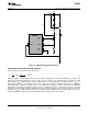
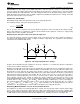
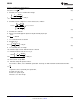
Figure 18. LM3444 External Components of the Buck Converter
The equation for an ideal inductor is:
(14)
Given a fixed inductor value, L, this equation states that the change in the inductor current over time is
proportional to the voltage applied across the inductor.
During the on-time, the voltage applied across the inductor is,
V
L(ON-TIME)
= V
BUCK
- (V
LED
+ V
DS(Q2)
+ I
L2
x R3) (15)
Since the voltage across the MOSFET switch (Q2) is relatively small, as is the voltage across sense resistor R3,
we can simplify this to approximately,
V
L(ON-TIME)
= V
BUCK
- V
LED
(16)
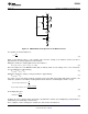
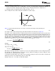
During the off-time, the voltage seen by the inductor is approximately:
V
L(OFF-TIME)
= V
LED
(17)
The value of V
L(OFF-TIME)
will be relatively constant, because the LED stack voltage will remain constant. If we
rewrite the equation for an inductor inserting what we know about the circuit during the off-time, we get:
(18)
Re-arranging this gives:
(19)
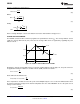
From this we can see that the ripple current (Δi) is proportional to off-time (t
OFF
) multiplied by a voltage which is
dominated by V
LED
divided by a constant (L2).
These equations can be rearranged to calculate the desired value for inductor L2.
Copyright © 2010–2013, Texas Instruments Incorporated Submit Documentation Feedback 15
Product Folder Links: LM3444