
Datasheet


I
L-PK(UNDIM)
=
750 mV
R3
I
AVE(UNDIM)
= I
L2-PK(UNDIM)
-
'i
L
2
I
L2-PK
= I
AVE
+
'i
L
2
t
t
OFF
t
ON
I
L2
(t)
I
AVE
I
L2-PK
'i
L
I
L2-MIN
L2 =
f
SW
x 'i
V
LED
V
LED
V
BUCK
1
K
1
u
V
LED
t
OFF
=
V
BUCK
f
SW
1
K
1
u
L2 #
t
OFF
x
V
LED
'i
LM3444
SNVS682C –NOVEMBER 2010–REVISED MAY 2013
www.ti.com
(20)
Where:
(21)
Finally:
(22)
Refer to “Design Example” section of the datasheet to better understand the design process.
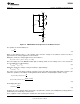
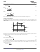
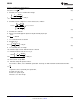
SETTING THE LED CURRENT
The LM3444 constant off-time control loop regulates the peak inductor current (I
L2
). The average inductor current
equals the average LED current (I
AVE
). Therefore the average LED current is regulated by regulating the peak
inductor current.
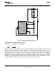
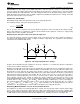
Figure 19. Inductor Current Waveform in CCM
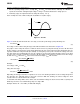
Knowing the desired average LED current, I
AVE
and the nominal inductor current ripple, Δi
L
, the peak current for
an application running in continuous conduction mode (CCM) is defined as follows:
(23)
Or the LED current would then be,
(24)
This is important to calculate because this peak current multiplied by the sense resistor R3 will determine when
the internal comparator is tripped. The internal comparator turns the control MOSFET off once the peak sensed
voltage reaches 750 mV.
(25)
16 Submit Documentation Feedback Copyright © 2010–2013, Texas Instruments Incorporated
Product Folder Links: LM3444