
Datasheet


V
BUCK(MIN)
=
2
90
2
x SIN(135
o
)
= 45V
V
BUCK(MIN)
=
2
V
AC-RMS(MIN)
#stages
x SIN(T)
V
AC-RMS-PK
2
V
AC
t
V
PEAK
LM3444
SNVS682C –NOVEMBER 2010–REVISED MAY 2013
www.ti.com
1. AC line operating voltage. This is usually 90V
AC
to 135V
AC
for North America. Although the LM3444 can
operate at much lower and higher input voltages a range is needed to illustrate the design process.
2. How many stages are implemented in the valley-fill circuit (1, 2 or 3).
In this example the most common valley-fill circuit will be used (two stages).
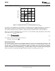
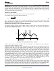
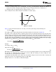
Figure 21. AC Line
Figure 21 shows the AC waveform. One can easily see that the peak voltage (V
PEAK
) will always be:
(27)
The voltage at V
BUCK
with a valley fill stage of two will look similar to the waveforms of Figure 20.
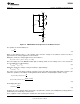
The purpose of the valley fill circuit is to allow the buck converter to pull power directly off of the AC line when
the line voltage is greater than its peak voltage divided by two (two stage valley fill circuit). During this time, the
capacitors within the valley fill circuit (C7 and C8) are charged up to the peak of the AC line voltage. Once the
line drops below its peak divided by two, the two capacitors are placed in parallel and deliver power to the buck
converter. One can now see that if the peak of the AC line voltage is lowered due to variations in the line voltage
the DC offset (V
DC
) will lower. V
DC
is the lowest value that voltage V
BUCK
will encounter.
(28)
Example:
Line voltage = 90V
AC
to 135V
AC
Valley-Fill = two stage
(29)
Depending on what type and value of capacitors are used, some derating should be used for voltage droop when
the capacitors are delivering power to the buck converter. With this derating, the lowest voltage the buck
converter will see is about 42.5V in this example.
To determine how many LEDs can be driven, take the minimum voltage the buck converter will see (42.5V) and
divide it by the worst case forward voltage drop of a single LED.
Example: 42.5V/3.7V = 11.5 LEDs (11 LEDs with margin)
18 Submit Documentation Feedback Copyright © 2010–2013, Texas Instruments Incorporated
Product Folder Links: LM3444