LM3464 Application Note 2071 LM3464A 4 Channel LED Driver Evaluation Board Literature Number: SNVA449C
National Semiconductor Application Note 2071 SH Wong June 3, 2011 Introduction Standard Settings of the Evaluation Board This evaluation board demonstrates the high power efficiency and outstanding output current accuracy of the LM3464A typical application circuit. With four LED strings connected, the total output power is about 50W. The schematic, bill of material and PCB layout drawing of the LM3464A evaluation board are provided in this document.
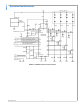
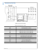
AN-2071 Evaluation Board Schematic 30127101 FIGURE 1. LM3464A Evaluation Board Schematic www.national.
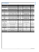
Designation Description Package Manufacturer Part # U1 LED Driver IC, LM3464A eTSSOP-28 eTSSOP-28 LM3464AMH Vendor NSC D1 Schottky Diode 40V 1.1A DO219AB DO219AB SL04-GS08 Vishay MOSFET N-CH 150V 29A D-PAK D-PAK FDD2572 Fairchild MOSFET N-CH 150V 50A TO252–3 TO252–3 IPD200N15N3 Infineon CIN Cap MLCC 100V 2.2uF X7R 1210 1210 GRM32ER72A225KA35L Murata CVCC Cap MLCC 10V 1uF X5R 0603 0603 GRM185R61A105KE36D Murata CDHC Cap MLCC 50V 0.
AN-2071 Connectors and Test Pins 30127102 FIGURE 2. Typical Connection Diagram Evaluation Board Quick Setup Procedures Terminal Designation www.national.
A LM3464A LED lighting system is basically consist of three main parts, the LM3464A evaluation board, an AC/DC power supply and an LED array containing four LED strings. In general, the LM3464A evaluation board can be regarded as four independent current sources that the dropout voltages on the current sources are being monitored by an internal circuit that generates the DHC signal. The LM3464A evaluation board is designed to drive 4 LED strings of 12 LEDs in series.
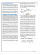
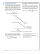
AN-2071 30127103 FIGURE 3. Changes of Rail Voltage Upon Power Up string connected to the system under possible temperatures, otherwise a ‘short fault’ may arise and results in immediate output channel latch-off to protect the MOSFETs from overheat. The VDHC_READY is can be adjusted following equation (5): Setting of VDHC_READY When VRAIL reaches VDHC_READY, the voltage at the VLedFB pin of the LM3464A equals 2.5V. As the voltage at the VLedFB pin reaches 2.
The LM3464A evaluation board is designed to drive 4 common anode LEDs strings of 12 serial LEDs per string. The board includes four turret connectors, LED1, LED2, LED3 and LED4 for cathode connections of the LED strings. The anode of the LED strings should connect to the positive power output terminal of the AC/DC power supply. By default, the output current for each output channel is set at 350mA.
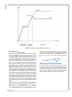
AN-2071 The default value of the CTHM on the LM3464A evaluation board is 68nF, which set the thermal foldback dimming frequency at 258Hz. Thermal foldback control is activated when the voltage at the Thermal pin, VThermalis in between 3.25V and 0.4V as shown in figure 5. Thermal foldback control begins when VThermal is below 3.25V. The LED current will be reduced to zero as VThermal falls below 0.4V.
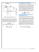
AN-2071 Design Example 30127114 FIGURE 6. Attaching NTC Thermistor to the LEDs A NTC thermistor is connected to the THM+ and THM- terminals of the LM3464A evaluation board as shown in figure 6 to activate the thermal foldback control function. Assuming that thermal foldback control is required to begin at 70°C LED chassis temperature and reduce 55% average LED current (45% dimming duty cycle) when the chassis temperature reaches 125°C. Using the NTC thermister NXFT15WB473FA1B from MURATA, which has 4.
AN-2071 of minimum duty cycle limit is governed by the following equation: output channels are turned OFF. In cascade operation, the DIM signal should only be applied to the MASTER unit. The LM3464A on the MASTER unit propagates the PWM dimming signal on its DIM pin to the slave units one by one through the SYNC pin. PWM dimming control is allowed when thermal foldback control is activated.
AN-2071 Cascade Operation 30127162 FIGURE 8. Cascading LM3464A Evaluation Boards for Output Channel Expansion 11 www.national.
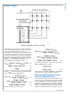
AN-2071 The total output power of the LED lighting system can be expanded by cascading the LM3464A evaluation boards. In cascade operation, the system involves one master unit and multiple slave units. Both master and slave units are LM3464A evaluation boards with minor modifications to program the LM3464A into master or slave modes. The connection diagram for cascade operation is shown in figure 8.
AN-2071 30127165 FIGURE 10. Additional Voltage Clamping Circuits for VRAIL(peak) > 80V/95V (LM3464A) evaluation board, the reverse voltage of the additional zener diodes must not exceed 95V. The resistors RDR1, RDR2, RDR3, RDR4 and RIN are resistors for absorbing the voltage difference across the DRx pins and VRAIL.
AN-2071 rent of the CMHZ5267B is 1.7mA at 75V zener voltage, the maximum allowable reverse current is 6.67mA at 500mW power dissipation. Given that the input current of the DRx pins of the LM3464A at 100V is 63uA maximum, if the DRx pin voltage is below 100V, the current flowing into the DRx pin (IDRx) is below 63uA. In the following calculations, IDRx is assumed to 63uA to reserve operation margin to compensate the characteristics variations of the components.
All curves taken at VIN = 48V with configuration in typical application for driving twelve power LEDs with four output channels active and output current per channel = 350mA. TA = 25°C, unless otherwise specified. Output Current Variation Efficiency (%) 30127120 30127121 VCC Variation (%) DHC in Cascade Operation 30127123 30127122 VSYNC at System Startup VSYNC of Master Unit 30127124 30127125 15 www.national.
AN-2071 Evaluation Board Layout 30127126 FIGURE 11. Top Layer and Top Overlay 30127127 FIGURE 12. Bottom Layer and Bottom Overlay www.national.
AN-2071 Notes 17 www.national.
LM3464A 4 Channel LED Driver Evaluation Board Notes For more National Semiconductor product information and proven design tools, visit the following Web sites at: www.national.com Products Design Support Amplifiers www.national.com/amplifiers WEBENCH® Tools www.national.com/webench Audio www.national.com/audio App Notes www.national.com/appnotes Clock and Timing www.national.com/timing Reference Designs www.national.com/refdesigns Data Converters www.national.com/adc Samples www.national.
IMPORTANT NOTICE Texas Instruments Incorporated and its subsidiaries (TI) reserve the right to make corrections, modifications, enhancements, improvements, and other changes to its products and services at any time and to discontinue any product or service without notice. Customers should obtain the latest relevant information before placing orders and should verify that such information is current and complete.