
Datasheet

1
2
5
43
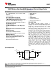
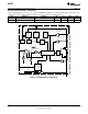
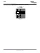
V
IN
SW
FB
EN
GND
L1:10uH
V
OUT
C
OUT
10uF
C
IN
4.7uF
LM3670
V
IN
2.5V to 5.5V
LM3670
www.ti.com
SNVS250E –NOVEMBER 2004–REVISED FEBRUARY 2013
LM3670 Miniature Step-Down DC-DC Converter for Ultra Low Voltage Circuits
Check for Samples: LM3670
1
FEATURES
APPLICATIONS
2
• V
OUT
= Adj (0.7V min), 1.2, 1.5, 1.6, 1.8, 1.875,
• Mobile Phones
2.5, 3.3V
• HandHeld
• 2.5V ≤ V
IN
≤ 5.5V
• PDAs
• 15 µA Typical Quiescent Current
• Palm-Top PCs
• 350 mA Maximum Load Capability
• Portable Instruments
• 1 MHz PWM Fixed Switching Frequency (typ.)
• Battery Powered Devices
• Automatic PFM/PWM Mode Switching
DESCRIPTION
• Available in Fixed Output Voltages as well as
The LM3670 step-down DC-DC converter is
an Adjustable Version
optimized for powering ultra-low voltage circuits from
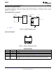
• SOT-23-5 Package
a single Li-Ion cell or 3 cell NiMH/NiCd batteries. It
• Low Drop Out Operation - 100% Duty Cycle
provides up to 350 mA load current, over an input
Mode
voltage range from 2.5V to 5.5V. There are several
different fixed voltage output options available as well
• Internal Synchronous Rectification for High
as an adjustable output voltage version.
Efficiency
• Internal Soft Start
The device offers superior features and performance
for mobile phones and similar portable applications
• 0.1 µA Typical Shutdown Current
with complex power management systems. Automatic
• Operates from a Single Li-Ion Cell or 3 Dell
intelligent switching between PWM low-noise and
NiMH/NiCd Batteries
PFM low-current mode offers improved system
• Only Three Tiny Surface-Mount External
control. During full-power operation, a fixed-frequency
1 MHz (typ). PWM mode drives loads from ∼70 mA to
Components Required (One Inductor, Two
350 mA max, with up to 95% efficiency. Hysteretic
Ceramic Capacitors)
PFM mode extends the battery life through reduction
• Current Overload Protection
of the quiescent current to 15 µA (typ) during light
current loads and system standby. Internal
synchronous rectification provides high efficiency (90
to 95% typ. at loads between 1 mA and 100 mA). In
shutdown mode (Enable pin pulled low) the device
turns off and reduces battery consumption to 0.1 µA
(typ.).
Typical Application
Figure 1. Fixed Output Voltage
1
Please be aware that an important notice concerning availability, standard warranty, and use in critical applications of
Texas Instruments semiconductor products and disclaimers thereto appears at the end of this data sheet.
2All trademarks are the property of their respective owners.
PRODUCTION DATA information is current as of publication date.
Copyright © 2004–2013, Texas Instruments Incorporated
Products conform to specifications per the terms of the Texas
Instruments standard warranty. Production processing does not
necessarily include testing of all parameters.