
Datasheet


– Input edge time capture
■ 16-bit PWM mode
– Simple PWM mode with software-programmable output inversion of the PWM signal
9.1 Block Diagram
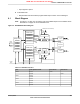
Note: In Figure 9-1 on page 337, the specific CCP pins available depend on the Stellaris device.
See Table 9-1 on page 337 for the available CCPs.
Figure 9-1. GPTM Module Block Diagram
TA Comparator
TB Comparator
GPTMTBR
GPTMAR
Clock / Edge
Detect
RTC Divider
Clock / Edge
Detect
TimerA
Interrupt
TimerB
Interrupt
System
Clock
0x0000 (Down Counter Modes)
0x0000 (Down Counter Modes)
32 KHz or
Even CCP Pin
Odd CCP Pin
En
En
TimerA Control
GPTMTAPMR
GPTMTAILR
GPTMTAMATCHR
GPTMTAPR
GPTMTAMR
TimerB Control
GPTMTBPMR
GPTMTBILR
GPTMTBMATCHR
GPTMTBPR
GPTMTBMR
Interrupt / Config
GPTMCFG
GPTMRIS
GPTMICR
GPTMMIS
GPTMIMR
GPTMCTL
Table 9-1. Available CCP Pins
Odd CCP PinEven CCP Pin16-Bit Up/Down CounterTimer
-CCP0TimerATimer 0
CCP1-TimerB
--TimerATimer 1
--TimerB
--TimerATimer 2
--TimerB
--TimerATimer 3
--TimerB
337June 18, 2012
Texas Instruments-Production Data
Stellaris
®
LM3S8962 Microcontroller
NRND: Not recommended for new designs.