
Datasheet


9.2 Signal Description
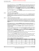
Table 9-2 on page 338 and Table 9-3 on page 338 list the external signals of the GP Timer module
and describe the function of each. The GP Timer signals are alternate functions for some GPIO
signals and default to be GPIO signals at reset. The column in the table below titled "Pin Assignment"
lists the possible GPIO pin placements for these GP Timer signals. The AFSEL bit in the GPIO
Alternate Function Select (GPIOAFSEL) register (page 311) should be set to choose the GP Timer
function. For more information on configuring GPIOs, see “General-Purpose Input/Outputs
(GPIOs)” on page 289.
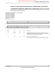
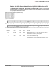
Table 9-2. General-Purpose Timers Signals (100LQFP)
DescriptionBuffer Type
a
Pin TypePin NumberPin Name
Capture/Compare/PWM 0.TTLI/O95CCP0
Capture/Compare/PWM 1.TTLI/O34CCP1
a. The TTL designation indicates the pin has TTL-compatible voltage levels.
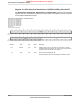
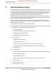
Table 9-3. General-Purpose Timers Signals (108BGA)
DescriptionBuffer Type
a
Pin TypePin NumberPin Name
Capture/Compare/PWM 0.TTLI/OE1CCP0
Capture/Compare/PWM 1.TTLI/OL6CCP1
a. The TTL designation indicates the pin has TTL-compatible voltage levels.
9.3 Functional Description
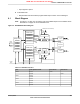
The main components of each GPTM block are two free-running 16-bit up/down counters (referred
to as TimerA and TimerB), two 16-bit match registers, two prescaler match registers, and two 16-bit
load/initialization registers and their associated control functions. The exact functionality of each
GPTM is controlled by software and configured through the register interface.
Software configures the GPTM using the GPTM Configuration (GPTMCFG) register (see page 349),
the GPTM TimerA Mode (GPTMTAMR) register (see page 350), and the GPTM TimerB Mode
(GPTMTBMR) register (see page 352). When in one of the 32-bit modes, the timer can only act as
a 32-bit timer. However, when configured in 16-bit mode, the GPTM can have its two 16-bit timers
configured in any combination of the 16-bit modes.
9.3.1 GPTM Reset Conditions
After reset has been applied to the GPTM module, the module is in an inactive state, and all control
registers are cleared and in their default states. Counters TimerA and TimerB are initialized to
0xFFFF, along with their corresponding load registers: the GPTM TimerA Interval Load
(GPTMTAILR) register (see page 363) and the GPTM TimerB Interval Load (GPTMTBILR) register
(see page 364). The prescale counters are initialized to 0x00: the GPTM TimerA Prescale
(GPTMTAPR) register (see page 367) and the GPTM TimerB Prescale (GPTMTBPR) register (see
page 368).
9.3.2 32-Bit Timer Operating Modes
This section describes the three GPTM 32-bit timer modes (One-Shot, Periodic, and RTC) and their
configuration.
June 18, 2012338
Texas Instruments-Production Data
General-Purpose Timers
NRND: Not recommended for new designs.