
Datasheet
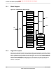

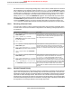
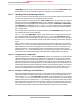

Table 15-1. Controller Area Network Signals (100LQFP)
DescriptionBuffer Type
a
Pin TypePin NumberPin Name
CAN module 0 receive.TTLI10CAN0Rx
CAN module 0 transmit.TTLO11CAN0Tx
a. The TTL designation indicates the pin has TTL-compatible voltage levels.
Table 15-2. Controller Area Network Signals (108BGA)
DescriptionBuffer Type
a
Pin TypePin NumberPin Name
CAN module 0 receive.TTLIG1CAN0Rx
CAN module 0 transmit.TTLOG2CAN0Tx
a. The TTL designation indicates the pin has TTL-compatible voltage levels.
15.3 Functional Description
The Stellaris CAN controller conforms to the CAN protocol version 2.0 (parts A and B). Message
transfers that include data, remote, error, and overload frames with an 11-bit identifier (standard)
or a 29-bit identifier (extended) are supported. Transfer rates can be programmed up to 1 Mbps.
The CAN module consists of three major parts:
■ CAN protocol controller and message handler
■ Message memory
■ CAN register interface
A data frame contains data for transmission, whereas a remote frame contains no data and is used
to request the transmission of a specific message object. The CAN data/remote frame is constructed
as shown in Figure 15-2 on page 553.
Figure 15-2. CAN Data/Remote Frame
Number
Of Bits
S
O
F
EOP
IFS
Bus
Idle
1
1
6
1
11 or 29
0 . . . 64
15
7
3
1
1
A
C
K
Data Field
Control
Field
R
T
R
Message Delimiter
Bus
Idle
Bit Stuffing
CAN Data Frame
Arbitration Field
CRC Sequence
CRC
Field
Acknowledgement
Field
End of
Frame
Field
Interframe
Field
Start
Of Frame
Remote
Transmission
Request
Delimiter
Bits
CRC
Sequence
553June 18, 2012
Texas Instruments-Production Data
Stellaris
®
LM3S8962 Microcontroller
NRND: Not recommended for new designs.