
Datasheet
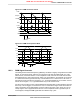
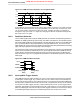
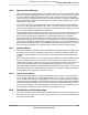
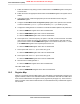
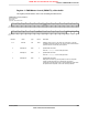
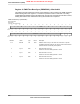

Figure 18-3. PWM Count-Down Mode
Load
Zero
CompB
CompA
Load
Zero
B
A
Dir
ADown
BDown
Figure 18-4. PWM Count-Up/Down Mode
Load
Zero
CompB
CompA
Load
Zero
B
A
Dir
BUp
AUp ADown
BDown
18.3.3 PWM Signal Generator
The PWM generator takes these pulses (qualified by the direction signal), and generates two PWM
signals. In Count-Down mode, there are four events that can affect the PWM signal: zero, load,
match A down, and match B down. In Count-Up/Down mode, there are six events that can affect
the PWM signal: zero, load, match A down, match A up, match B down, and match B up. The match
A or match B events are ignored when they coincide with the zero or load events. If the match A
and match B events coincide, the first signal, PWMA, is generated based only on the match A event,
and the second signal, PWMB, is generated based only on the match B event.
For each event, the effect on each output PWM signal is programmable: it can be left alone (ignoring
the event), it can be toggled, it can be driven Low, or it can be driven High. These actions can be
used to generate a pair of PWM signals of various positions and duty cycles, which do or do not
overlap. Figure 18-5 on page 664 shows the use of Count-Up/Down mode to generate a pair of
center-aligned, overlapped PWM signals that have different duty cycles.
663June 18, 2012
Texas Instruments-Production Data
Stellaris
®
LM3S8962 Microcontroller
NRND: Not recommended for new designs.