
Datasheet

Register 13: PWM0 Interrupt and Trigger Enable (PWM0INTEN), offset 0x044
Register 14: PWM1 Interrupt and Trigger Enable (PWM1INTEN), offset 0x084
Register 15: PWM2 Interrupt and Trigger Enable (PWM2INTEN), offset 0x0C4
These registers control the interrupt and ADC trigger generation capabilities of the PWM generators
(PWM0INTEN controls the PWM generator 0 block, and so on). The events that can cause an
interrupt or an ADC trigger are:
■ The counter being equal to the load register
■ The counter being equal to zero
■ The counter being equal to the comparator A register while counting up
■ The counter being equal to the comparator A register while counting down
■ The counter being equal to the comparator B register while counting up
■ The counter being equal to the comparator B register while counting down
Any combination of these events can generate either an interrupt, or an ADC trigger; though no
determination can be made as to the actual event that caused an ADC trigger if more than one is
specified.
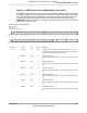
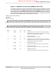
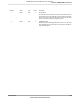
PWM0 Interrupt and Trigger Enable (PWM0INTEN)
Base 0x4002.8000
Offset 0x044
Type R/W, reset 0x0000.0000
16171819202122232425262728293031
reserved
ROROROROROROROROROROROROROROROROType
0000000000000000Reset
0123456789101112131415
IntCntZeroIntCntLoad
IntCmpAUIntCmpADIntCmpBUIntCmpBD
reserved
TrCntZeroTrCntLoad
TrCmpAUTrCmpADTrCmpBUTrCmpBDreserved
R/WR/WR/WR/WR/WR/WROROR/WR/WR/WR/WR/WR/WROROType
0000000000000000Reset
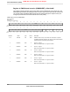
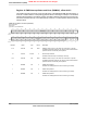
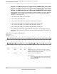
DescriptionResetTypeNameBit/Field
Software should not rely on the value of a reserved bit. To provide
compatibility with future products, the value of a reserved bit should be
preserved across a read-modify-write operation.
0x00ROreserved31:14
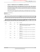
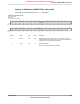
Trigger for Counter=Comparator B Down
DescriptionValue
An ADC trigger pulse is output when the counter matches the
value in the PWMnCMPB register value while counting down.
1
No ADC trigger is output.0
0R/WTrCmpBD13
June 18, 2012680
Texas Instruments-Production Data
Pulse Width Modulator (PWM)
NRND: Not recommended for new designs.