LM4051 LM4051 Precision Micropower Shunt Voltage Reference Literature Number: SNOS491C
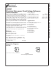
LM4051 Precision Micropower Shunt Voltage Reference General Description j Low output noise Ideal for space critical applications, the LM4051 precision voltage reference is available in the sub-miniature (3 mm x 1.3 mm) SOT-23 surface-mount package. The LM4051’s advanced design eliminates the need for an external stabilizing capacitor while ensuring stability with any capacitive load, thus making the LM4051 easy to use. Further reducing design effort is the availability of a fixed (1.
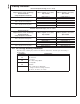
LM4051 Ordering Information Industrial Temperature Range (−40˚C to +85˚C) Reverse Breakdown Voltage Tolerance at 25˚C and Average Reverse Breakdown Voltage Temperature Coefficient ± 0.1%, 50 ppm/˚C max (A grade) ± 0.2%, 50 ppm/˚C max (B grade) ± 0.5%, 50 ppm/˚C max (C grade) LM4051 Supplied as 1000 Units, Tape and Reel LM4051 Supplied as 3000 Units, Tape and Reel LM4051AIM3-1.2 LM4051AIM3X-1.2 LM4051AIM3-ADJ LM4051AIM3X-ADJ LM4051BIM3-1.2 LM4051BIM3X-1.
If Military/Aerospace specified devices are required, please contact the National Semiconductor Sales Office/ Distributors for availability and specifications. Reverse Current 20 mA Forward Current 10 mA 2 kV Machine Model (Note 3) 200V See AN-450 “Surface Mounting Methods and Their Effect on Product Reliability” for other methods of soldering surface mount devices.
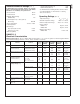
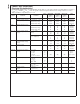
LM4051 LM4051-ADJ (Adjustable) Electrical Characteristics Boldface limits apply for TA = TJ = TMIN to TMAX; all other limits TJ = 25˚C unless otherwise specified (SOT-23, see (Note 7) , IRMIN ≤ IR ≤ 12 mA, VREF ≤ VOUT ≤ 10V. The grades A, B and C designate initial Reference Voltage Tolerances of ± 0.1%, ± 0.2% and ± 0.5%, respectively for VOUT = 5V.
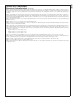
LM4051 LM4051-ADJ (Adjustable) Electrical Characteristics (Continued) Note 1: Absolute Maximum Ratings indicate limits beyond which damage to the device may occur. Operating Ratings indicate conditions for which the device is functional, but do not guarantee specific performance limits. For guaranteed specifications and test conditions, see the Electrical Characteristics. The guaranteed specifications apply only for the test conditions listed.
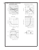
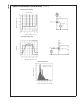
LM4051 Typical Performance Characteristics Temperature Drift for Different Average Temperature Coefficient Output Impedance vs Frequency 10122219 10122204 Noise Voltage Reverse Characteristics and Minimum Operating Current 10122205 10122209 Start-Up Characteristics 10122208 10122207 www.national.
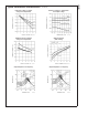
LM4051 Typical Performance Characteristics (Continued) Reference Voltage vs Output Voltage and Temperature Reference Voltage vs Temperature and Output Voltage 10122211 10122210 Feedback Current vs Output Voltage and Temperature Output Saturation (SOT-23 Only) 10122212 10122233 Output Impedance vs Frequency Output Impedance vs Frequency 10122213 10122214 7 www.national.
LM4051 Typical Performance Characteristics (Continued) Reverse Characteristics 10122216 10122215 Large Signal Response 10122218 10122217 Thermal Hysteresis 10122250 www.national.
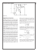
LM4051 Functional Block Diagram 10122221 *LM4051-ADJ only **LM4051-1.2 only LM4051 even when the supply voltage is at its minimum and the load current is at its maximum value. When the supply voltage is at its maximum and IL is at its minimum, RS should be large enough so that the current flowing through the LM4051 is less than 12 mA. RS should be selected based on the supply voltage, (VS), the desired load and operating current, (IL and IQ), and the LM4051’s reverse breakdown voltage, VR.
LM4051 Typical Applications 10122222 FIGURE 1. Shunt Regulator 10122234 FIGURE 2. Adjustable Shunt Regulator 10122224 FIGURE 3. Bounded amplifier reduces saturation-induced delays and can prevent succeeding stage damage. Nominal clamping voltage is ± VO (LM4051’s reverse breakdown voltage) +2 diode VF. www.national.
LM4051 Typical Applications (Continued) 10122226 10122220 FIGURE 7. Bidirectional Clamp ± 2.4V FIGURE 4. Voltage Level Detector 10122223 FIGURE 5. Voltage Level Detector 10122235 FIGURE 8. Bidirectional Adjustable Clamp ± 18V to ± 2.4V 10122225 FIGURE 6. Fast Positive Clamp 2.4V + VD1 11 10122236 www.national.com FIGURE 9. Bidirectional Adjustable Clamp ± 2.
LM4051 Typical Applications (Continued) 10122237 FIGURE 10. Simple Floating Current Detector 10122238 FIGURE 11. Current Source Note 11: *D1 can be any LED, VF = 1.5V to 2.2V at 3 mA. D1 may act as an indicator. D1 will be on if ITHRESHOLD falls below the threshold current, except with I = O. www.national.
LM4051 Typical Applications (Continued) 10122239 FIGURE 12. Precision Floating Current Detector 10122229 10122228 FIGURE 13. Precision 1 µA to 1 mA Current Sources 13 www.national.
LM4051 Precision Micropower Shunt Voltage Reference Physical Dimensions inches (millimeters) unless otherwise noted Plastic Surface Mount Package (M3) NS Package Number MF03A (JEDEC Registration TO-236AB) National does not assume any responsibility for use of any circuitry described, no circuit patent licenses are implied and National reserves the right at any time without notice to change said circuitry and specifications. For the most current product information visit us at www.national.com.
IMPORTANT NOTICE Texas Instruments Incorporated and its subsidiaries (TI) reserve the right to make corrections, modifications, enhancements, improvements, and other changes to its products and services at any time and to discontinue any product or service without notice. Customers should obtain the latest relevant information before placing orders and should verify that such information is current and complete.