
Datasheet
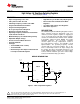
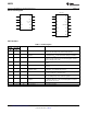
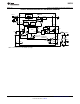
Table Of Contents
V
IN
SW
BST
LM5010
V
CC
SS
R
ON
/ SD
8V - 75V
Input
C1
R
ON
R2
R1
C2
V
OUT
L1
C3
C4
D1
C6
RTN
I
SEN
S
GND
FB
SHUTDOWN
LM5010
www.ti.com
SNVS307F –SEPTEMBER 2004–REVISED FEBRUARY 2013
High-Voltage 1-A Step-Down Switching Regulator
Check for Samples: LM5010
1
FEATURES
APPLICATIONS
2
• Input Voltage Range: 8V to 75V
• High Efficiency Point-Of-Load (POL) Regulator
• Valley Current Limit At 1.25A • Non-Isolated Telecommunications Buck
Regulator
• Switching Frequency Can Exceed 1 MHz
• Secondary High Voltage Post Regulator
• Integrated N-Channel Buck Switch
• Automotive Systems
• Integrated Startup Regulator
• No Loop Compensation Required
DESCRIPTION
• Ultra-Fast Transient Response
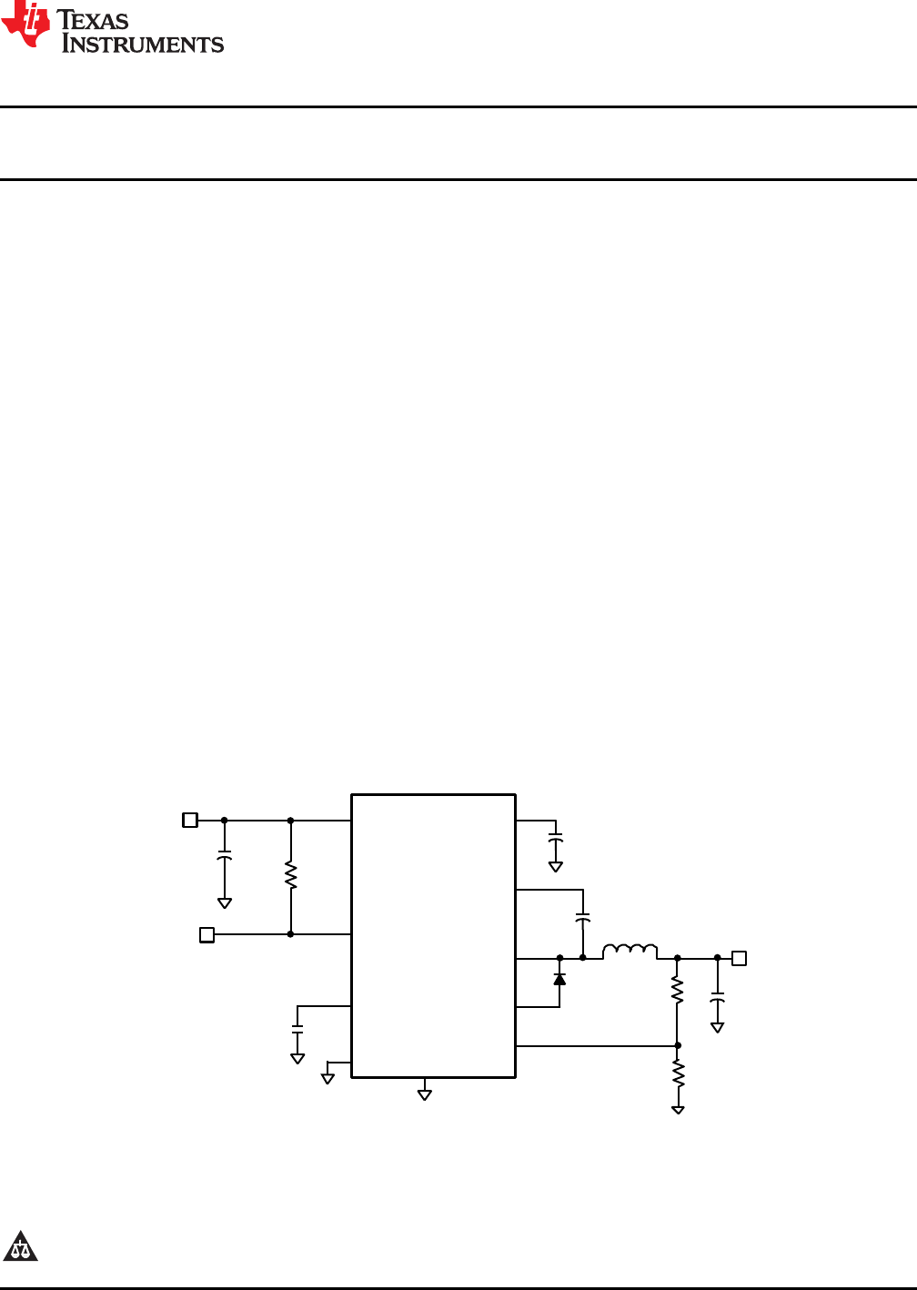
The LM5010 Step Down Switching Regulator features
• Operating Frequency Remains Constant With
all the functions needed to implement a low cost,
Load and Line Variations
efficient, buck bias regulator capable of supplying in
excess of 1A load current. This high voltage regulator
• Maximum Duty Cycle Limited During Startup
contains an N-Channel Buck Switch, and is available
• Adjustable Output Voltage
in thermally enhanced 10-pin WSON and 14-pin
• Precision 2.5V Feedback Reference
HTSSOP packages. The hysteretic regulation
scheme requires no loop compensation, results in
• Thermal shutdown
fast load transient response, and simplifies circuit
• Packages
implementation. The operating frequency remains
– 10-Pin WSON (4 mm x 4 mm)
constant with line and load variations due to the
– 14-Pin HTSSOP inverse relationship between the input voltage and
the on-time. The valley current limit detection is set at
– Both Packages Have Exposed Thermal Pad
1.25A. Additional features include: V
CC
under-voltage
For Improved Heat Dissipation
lockout, thermal shutdown, gate drive under-voltage
lockout, and maximum duty cycle limiter.
DEVICE INFORMATION
Figure 1. Basic Step-Down Regulator
1
Please be aware that an important notice concerning availability, standard warranty, and use in critical applications of
Texas Instruments semiconductor products and disclaimers thereto appears at the end of this data sheet.
2All trademarks are the property of their respective owners.
PRODUCTION DATA information is current as of publication date.
Copyright © 2004–2013, Texas Instruments Incorporated
Products conform to specifications per the terms of the Texas
Instruments standard warranty. Production processing does not
necessarily include testing of all parameters.