
Datasheet

LM5025
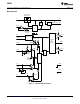
UVLO
PGND
AGND
COMP
OUT_A
OUT_B
V
CC
SS
Rt
SYNC
REF
TIME
RAMP
CS1
V
IN
CS2
V
IN
35 - 78V
V
OUT
3.3V
UP/DOWN
SYNC
ERROR
AMP &
ISOLATION
LM5025
www.ti.com
SNVS265B –DECEMBER 2003–REVISED MARCH 2013
Active Clamp Voltage Mode PWM Controller
Check for Samples: LM5025
1
FEATURES
DESCRIPTION
The LM5025 PWM controller contains all of the
2
• Internal Start-up Bias Regulator
features necessary to implement power converters
• 3A Compound Main Gate Driver
utilizing the Active Clamp / Reset technique. The
• Programmable Line Under-Voltage Lockout
device can be configured to control either a P-
(UVLO) with Adjustable Hysteresis
Channel clamp switch or an N-Channel clamp switch.
With the active clamp technique, higher efficiencies
• Voltage Mode Control with Feed-Forward
and greater power densities can be realized
• Adjustable Dual Mode Over-Current Protection
compared to conventional catch winding or RDC
• Programmable Overlap or Deadtime between
clamp / reset techniques. Two control outputs are
the Main and Active Clamp Outputs
provided, the main power switch control (OUT_A) and
the active clamp switch control (OUT_B). The active
• Volt x Second Clamp
clamp output can be configured for either a specified
• Programmable Soft-start
overlap time (for P-Channel switch applications) or a
• Leading Edge Blanking
specified deadtime (for N_Channel applications). The
two internal compound gate drivers parallel both MOS
• Single Resistor Programmable Oscillator
and Bipolar devices, providing superior gate drive
• Oscillator UP / DOWN Sync Capability
characteristics. This controller is designed for high-
• Precision 5V Reference
speed operation including an oscillator frequency
range up to 1MHz and total PWM and current sense
• Thermal Shutdown
propagation delays less than 100ns. The LM5025
includes a high-voltage start-up regulator that
PACKAGES
operates over a wide input range of 13V to 90V.
• TSSOP-16
Additional features include: Line Under Voltage
Lockout (UVLO), softstart, oscillator UP/DOWN sync
• WSON-16 (5x5 mm) Thermally Enhanced
capability, precision reference and thermal shutdown.
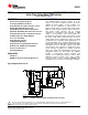
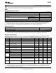
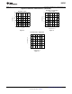
Typical Application Circuit
Figure 1. Simplified Active Clamp Forward Power Converter
1
Please be aware that an important notice concerning availability, standard warranty, and use in critical applications of
Texas Instruments semiconductor products and disclaimers thereto appears at the end of this data sheet.
2All trademarks are the property of their respective owners.
PRODUCTION DATA information is current as of publication date.
Copyright © 2003–2013, Texas Instruments Incorporated
Products conform to specifications per the terms of the Texas
Instruments standard warranty. Production processing does not
necessarily include testing of all parameters.